JVC BR-DV6000U User Manual - Page 12
REMOTE/LOCAL] switch, INPUT SELECT] switch, AUDIO OUTPUT] switch
 |
UPC - 046838325557
View all JVC BR-DV6000U manuals
Add to My Manuals
Save this manual to your list of manuals |
Page 12 highlights
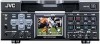
NAMES AND FUNCTIONS OF PARTS - Front panel - (continued) Mini MENU DISP RESET SEARCH- SET SEARCH+ MIC HOLD BLANK CUE UP PHONES REC LEVEL CH-1/3 CH-2/4 PROFESSIONAL BR-DV6000 OPERATE A.DUB REC PLAY PAUSE EJECT REW STOP FF AUDIO INPUT COUNTER MONITOR OUTPUT SELECT CTL L CH-1/2 DV TC MIX MIX LINE UB R CH-3/4 Y/C (CPN) REMOTE LOCAL 4 [REMOTE/LOCAL] switch 9 87654 5 [INPUT SELECT] switch This switch is used to select how BR-DV6000 This switch is used to select input signals. is to be operated. DV : For DV signals of the DV IN/OUT LOCAL : Use this setting if BR-DV6000 is to terminal (IEEE1394) be controlled with the key operation LINE : For inputting the composite images of the unit. of the LINE IN terminal and ana- REMOTE : Use this setting if BR-DV6000 is to log audio signals. be controlled using the edit control- Y/C (CPN) : For inputting theYC separate video ler connected to the REMOTE 1 (9- signal of the Y/C IN terminal and PIN) terminal or REMOTE 2 (12- the component video signal of the PIN) terminal. COMPONENT IN terminal. The When it is set to REMOTE, settings selection of the YC separate sig- can be performed at the REMOTE nal or the component video signal (1/2) MENU screen to enable/dis- can be done with VIDEO INPUT able operation via the 9-PIN or 12- SEL in the VIDEO MENU screen. PIN REMOTE terminal. For audio, analog sound is input. The 9-PIN REMOTE 1 terminal can be selected using REMOTE SEL 9 PIN while the 12-PIN REMOTE 2 Note Switching is invalid during recording. terminal can be selected with RE- MOTE SEL JVC. 6 [AUDIO OUTPUT] switch Memo ● To control BR-DV6000 with the SERIAL REMOTE terminal or DV terminal, this switch setting can be set up with REMOTE SEL SERIAL or REMOTE SEL DV in the REMOTE (1/2) MENU screen. (☞ Page 75) ● If it is set to REMOTE, the buttons that can be operated from the unit are selectable from LOCAL FUNCTION in the REMOTE (1/2) MENU screen. Use this switch to select the audio channel from the headphone terminal and the AUDIO OUT terminal located on the rear panel. This switch is valid in the following conditions. • During playback of tapes recorded in the 32k audio mode • In the EE mode for DV input in the 32k audio mode • During audio dubbing CH-1/2 : For outputting the sound of the channels CH1 and CH2. MIX : For outputting the mixed sound of CH1 and CH3 from the CH-1/3 AU- DIO OUT terminal and the mixed sound of CH2 and CH4 from the CH- 2/4 AUDIO OUT terminal. CH-3/4 : For outputting the sound of CH3 and CH4. 12
-
 1
1 -
2
-
3
-
4
-
5
-
6
-
 7
7 -
 8
8 -
 9
9 -
 10
10 -
 11
11 -
 12
12 -
 13
13 -
 14
14 -
 15
15 -
 16
16 -
 17
17 -
18
-
19
-
20
-
21
-
22
-
23
-
24
-
25
-
26
-
27
-
28
-
29
-
30
-
31
-
32
-
33
-
34
-
35
-
36
-
37
-
38
-
39
-
40
-
41
-
42
-
43
-
44
-
45
-
46
-
47
-
48
-
49
-
50
-
51
-
52
-
53
-
54
-
55
-
56
-
57
-
58
-
59
-
60
-
61
-
62
-
63
-
64
-
65
-
66
-
67
-
68
-
69
-
70
-
71
-
72
-
73
-
74
-
75
-
76
-
77
-
78
-
79
-
80
-
81
-
82
-
83
-
84
-
85
-
86
-
87
-
88
-
89
-
90
-
91
-
92
-
93
-
94
-
95
-
96
-
97
-
98
-
99
-
100
-
101
-
102
-
103
-
104
-
105
-
106
 |
 |
