JVC BR-DV6000U User Manual - Page 30
Connection
 |
UPC - 046838325557
View all JVC BR-DV6000U manuals
Add to My Manuals
Save this manual to your list of manuals |
Page 30 highlights
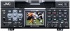
CONNECTION - Connecting audio signals - Audio output of VCR Input Slot cover for optional board DV Analog audio (2 channels) VIDEO LINE Y/C COMPONENT IN R-Y B-Y Y OUT REMOTE2 IN OUT AUDIO CH 1/3 CH 2/4 IN MONITOR OUT SIGNAL GND DC12V IN SYNC IN DV IN/OUT OUT TIME CODE IN OUT OFF REC PLAY SERIAL REMOTE TIMER OUT MONITOR OUT REMOTE1 Monaural Stereo MONITOR OUT analog (monaural) DV Analog audio (2 channels) Output Microphone Headphone Monitor Audio input of VCR Ⅵ Output signal When BR-DV6000 is in the STOP, REC or EDIT mode, signals (EE sound), which have been input, are output. During the PLAYBACK mode (including the playback of the pre-roll part during editing), the playback sound is output. However, in the edit mode with analog input, signals cannot be output to the DV OUT terminal properly. ● Analog signal CH 1/3, CH 2/4 AUDIO terminal (RCAן2). There are analog audio terminals for 2 channels. For the DV format, tracks are available for 4 channels (in the 32kHz audio mode). • In the 32kHz mode, from which one of the 4 channels sound is output can be selected with the AUDIO OUTPUT switch on the front panel. (Refer to the table on the right.) ● Headphone terminal Sound can be checked in stereo using a headphone. The volume can be adjusted with the PHONES switch on the front panel. • The channel to be output from this terminal in the 32kHz audio mode can be selected with the AUDIO OUTPUT switch. (Refer to the table on the right.) AUDIO OUTPUT switches and output channels In the following cases, the channels that receive output from the AUDIO OUTPUT terminal vary according to the setting of the AUDIO OUTPUT switch. The table below shows the channels. • During playback of tapes recorded in the 32kHz audio mode. • During audio dubbing. • In the EE mode of DV input in the 32kHz audio mode. AUDIO OUTPUT switch CH1/2 MIX CH3/4 AUDIO OUT terminal CH1/3 (L) CH1 CH1/3 CH3 CH2/4 (R) CH2 CH2/4 CH4 • In the 48kHz audio mode or during normal recording, output goes to CH1 and CH2 regardless of the setting of the switch. 30
-
 1
1 -
2
-
3
-
4
-
5
-
6
-
7
-
8
-
9
-
10
-
11
-
12
-
13
-
14
-
15
-
16
-
17
-
18
-
19
-
20
-
21
-
22
-
23
-
24
-
 25
25 -
 26
26 -
 27
27 -
 28
28 -
 29
29 -
 30
30 -
 31
31 -
 32
32 -
 33
33 -
 34
34 -
 35
35 -
36
-
37
-
38
-
39
-
40
-
41
-
42
-
43
-
44
-
45
-
46
-
47
-
48
-
49
-
50
-
51
-
52
-
53
-
54
-
55
-
56
-
57
-
58
-
59
-
60
-
61
-
62
-
63
-
64
-
65
-
66
-
67
-
68
-
69
-
70
-
71
-
72
-
73
-
74
-
75
-
76
-
77
-
78
-
79
-
80
-
81
-
82
-
83
-
84
-
85
-
86
-
87
-
88
-
89
-
90
-
91
-
92
-
93
-
94
-
95
-
96
-
97
-
98
-
99
-
100
-
101
-
102
-
103
-
104
-
105
-
106
 |
 |
