JVC BR-DV6000U User Manual - Page 16
VIDEO Y/C IN] terminal 4-PIN
 |
UPC - 046838325557
View all JVC BR-DV6000U manuals
Add to My Manuals
Save this manual to your list of manuals |
Page 16 highlights
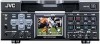
NAMES AND FUNCTIONS OF PARTS 1 6 7 !@ - Rear panel - 2 3 4 VIDEO LINE Y/C COMPONENT IN R-Y B-Y Y OUT REMOTE2 IN OUT AUDIO CH 1/3 CH 2/4 IN MONITOR OUT SIGNAL GND DC12V IN SYNC IN DV IN/OUT OUT TIME CODE IN OUT OFF REC PLAY SERIAL REMOTE TIMER OUT MONITOR OUT REMOTE1 $ 5809 1 [VIDEO LINE IN] terminal (BNC) This is the input terminal for composite video signals. • To input video via this terminal, set the IN- PUT SELECT switch located on the front panel to "LINE". 2 [VIDEO Y/C IN] terminal (4-PIN) This is the input terminal for YC separate video signals. • To input video via this terminal, the following settings are required. Set VIDEO INPUT SEL in the VIDEO Menu screen to "Y/C". Set the INPUT SELECT switch located on the front panel to "Y/C (CPN)". • When wide-screen ID signals are input, the wide-screen ID signal is recorded. 3 [VIDEO LINE OUT] terminal (BNC) This is the output terminal for composite video signals. 4 [VIDEO Y/C OUT] terminal (4-PIN) This is the output terminal for Y/C separate video signals. • When tapes that have recorded wide-screen signals are played back, the wide-screen ID signal is output. #% 5 [VIDEO MONITOR OUT] terminal (BNC) This terminal is for connecting to a monitor-TV. • It outputs composite video signals. • It displays the Menu setting screen, Date/ Time setting screen and warning information. • If DISPLAY in the DISPLAY Menu screen is set to "ON" or "AUTO", information will be displayed on-screen, e.g., the operation mode, date/time and counter. (☞ Page 20) 6 [COMPONENT IN] terminal (BNCן3) This is the input terminal for component video signals (Y/R-Y/B-Y). The signal level is high (ß cam spec). • To input video of this terminal, the following settings are required. Set VIDEO INPUT SEL in the VIDEO Menu screen to COMPONENT. Set the INPUT SELECT switch located on the front panel to "Y/C (CPN)". 7 [COMPONENT OUT] terminal (BNCן3) This is the output terminal for component video signals (Y/R-Y/B-Y). The signal level is high (ß cam spec). Memo Whether or not to enable SET UP for analog signals (composite, YC separate and component signals) can be selected with SET UP in the VIDEO Menu screen (for NTSC only). 16
-
 1
1 -
2
-
3
-
4
-
5
-
6
-
7
-
8
-
9
-
10
-
 11
11 -
 12
12 -
 13
13 -
 14
14 -
 15
15 -
 16
16 -
 17
17 -
 18
18 -
 19
19 -
 20
20 -
 21
21 -
22
-
23
-
24
-
25
-
26
-
27
-
28
-
29
-
30
-
31
-
32
-
33
-
34
-
35
-
36
-
37
-
38
-
39
-
40
-
41
-
42
-
43
-
44
-
45
-
46
-
47
-
48
-
49
-
50
-
51
-
52
-
53
-
54
-
55
-
56
-
57
-
58
-
59
-
60
-
61
-
62
-
63
-
64
-
65
-
66
-
67
-
68
-
69
-
70
-
71
-
72
-
73
-
74
-
75
-
76
-
77
-
78
-
79
-
80
-
81
-
82
-
83
-
84
-
85
-
86
-
87
-
88
-
89
-
90
-
91
-
92
-
93
-
94
-
95
-
96
-
97
-
98
-
99
-
100
-
101
-
102
-
103
-
104
-
105
-
106
 |
 |
