JVC GY-DV300REM Instruction Manual - Page 12
Front Top
 |
View all JVC GY-DV300REM manuals
Add to My Manuals
Save this manual to your list of manuals |
Page 12 highlights
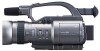
CONTROLS, INDICATORS AND CONNECTORS Front Section ] \ ` CONTROLS, INDICATORS AND CONNECTORS Top Section $3 START/ T STOP W EJECT W VOLUME T $1 $2 $4 \ Built-in microphone Built-in monaural microphone. ● To use this microphone, set the MIC1 INPUT SEL item to INT on the SYSTEM [1/2] menu screen. ] [MIC 1] Microphone 1 input connector (XLR3P) Connect an external microphone to this connector. Monaural signals are recorded. ● To use the microphone connected to this connector, set the MIC1 INPUT SEL item to XLR on the SYSTEM [1/2] menu screen. ● To use a microphone requiring +48 V power supply (phantom microphone), set the +48V MIC1 item on the SYSTEM [1/2] menu screen to ON. This connector will then supply +48 V DC current. When using a microphone other than a phantom microphone, set the +48V MIC1 item to OFF. ` [MIC 2] Microphone 2 input connector (XLR3P) Connect an external microphone to this connector. Monaural signals are recorded. ● To use a microphone requiring +48 V power supply (phantom microphone), set the +48V MIC2 item on the SYSTEM [1/2] menu screen to ON. This connector will then supply +48 V DC current. When using a microphone other than a phantom microphone, set the +48V MIC2 item to OFF. Memo: • The audio input channel is selected with the CH-1/CH-2 audio input selector switch M. • To reduce the wind noise of the microphone, set the WIND CUT MIC1/MIC2 item on the SYSTEM [1/2] menu screen to ON. a ZOOM/Playback sound level adjustment lever ● This works as the zoom lever in the shooting mode. Pressing the lever in the T direction narrows the lens angle perspective for telephoto shots. Pressing it in the W direction increases the angle of the lens for a wider shooting angle. The harder the lever is pressed, the quicker the zoom action. ● In the VTR playback mode, this lever is used for adjusting the playback sound level. Pressing the lever in the + direction increases the volume level, and pressing in the - direction decreases the level. b [EJECT] Eject switch Slide to the side when inserting or ejecting the videocassette. Sliding this button and then opening the cassette cover will eject the cassette. c [ZOOM] Zoom lever Lever for zoom operation from the handle top section. ● In the shooting mode, pressing this lever in the T direction narrows the lens angle perspective for telephoto shots. Pressing it in the W direction increases the angle of the lens for a wider shooting angle. The zoom speed of this zoom lever is selected with the HANDLE ZOOM item on the SYSTEM [2/2] menu screen. d [START/STOP] REC START/STOP button Button for start and stop of recording from the handle top section. When the GY-DV300 is in the shooting mode, pressing this button starts the recording. Pressing the button during a recording engages the recording-standby mode. TENTATIVE 20 21
-
 1
1 -
2
-
3
-
4
-
5
-
6
-
 7
7 -
 8
8 -
 9
9 -
 10
10 -
 11
11 -
 12
12 -
 13
13 -
 14
14 -
 15
15 -
 16
16 -
 17
17 -
18
-
19
-
20
-
21
-
22
-
23
-
24
-
25
-
26
-
27
-
28
-
29
-
30
-
31
-
32
-
33
-
34
-
35
-
36
-
37
-
38
-
39
-
40
-
41
-
42
-
43
-
44
-
45
-
46
-
47
-
48
-
49
-
50
-
51
-
52
-
53
-
54
-
55
-
56
-
57
 |
 |
