JVC GY-DV300REM Instruction Manual - Page 44
Outputting CH- 3/ CH- 4 Channel Sound, EXTERNAL COMPONENTS
 |
View all JVC GY-DV300REM manuals
Add to My Manuals
Save this manual to your list of manuals |
Page 44 highlights
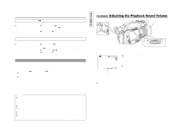
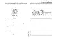
PLAYBACK Outputting CH-3/CH-4 Channel Sound 4 channels are available when the DV format is recorded with 12-bit, 32 kHz audio sampling. The GYDV300 records audio on the CH-1 and CH-2 channels. When the GY-DV300 is used for playback of tapes with sound recorded on the CH-3 and CH-4 channels on another unit, the PB AUDIO SELECT item on the VTR menu screen must be set. MODE switch MODE CAM-B CAM-A VTR GAIN SHUTTER MENU button MENU SELECT dial TOP MENU screen MENU VTR SET . . SY ST EM S ET . . D I S PL AY SET . . C L OC K / T C . . MENU AL L RESET EX I T CANCE L VTR menu screen V TR PB AUD I O SELECT CH1 / 2 REM F F / REW MODE F F / REW P AG E BACK DRUM HOUR 0 00200 Setting Setting Ⅲ Confirm that the MODE switch is set to "VTR". 1. Press the MENU button to display the TOP MENU screen. 2. Using the SELECT dial, select the VTR SET item, and then press the SELECT dial. ● The VTR menu screen is displayed. 3. Rotate the SELECT dial to align the cursor (f) with the PB. AUDIO SELECT item, and then press the SELECT dial. ● The setting area starts blinking. 4. Rotate the SELECT dial to make the settings. CH1/CH2 : To reproduce the sound recorded during shooting. MIX : To simultaneously reproduce the sound recorded during shooting and the sound after-recorded on CH-3 and CH-4. CH3/CH4 : To reproduce the sound after-recorded on CH-3 and CH-4. 5. When the SELECT dial is pressed, the set value is confirmed. 6. To return to the normal screen, use either of the following methods. ● Press the MENU button or ● Return to the TOP MENU screen and then select the EXIT item before pressing the SELECT dial. 83 TENTATIVE Connecting a Video Component EXTERNAL COMPONENTS with DV Connector Connecting the GY-DV300 to another video component equipped with DV I/O connector (IEEE1394 standard) using a DV cable (optional) enables dubbing of digital signals with high picture quality and high-quality sound. When used in a cold environment, this becomes 3 minutes regardless of the setting. (E MODEL) Memo: The GY-DV300 cannot be used as the recording component. (E MODEL) MODE switch BAR button MODE CAM-B CAM-A VTR BAR AW REC START/STOP button DV connector DV connector AW button DV cable: VX-DV130 (4P-4P) VX-DV230 (4P-4P) When using the GY-DV300 as playback unit (dubbing to another videocassette) ● Pressing the BAR button during playback engages the still mode. ● When a still picture is dubbed, the dubbed picture will be coarse. ● When the BR-DV600A's TC DUPLICATE mode is used, the time code data played back on the GY-DV300 can also be dubbed. 1. Connect the units with the DV cable. 2. Turn ON both units. 3. Set the MODE switch on the GY-DV300 to "VTR". 4. Insert the videocassettes. GY-DV300: Insert the recorded videocassette. Recording unit: Insert the videocassette to be dubbed to. 5. Press the BAR button on the GY-DV300 to start playback. 6. Start recording on the recording unit. For details, see the instructions to the unit used for recording. 7. When dubbing is completed. Stop recording on the recording unit, and then press the AW button on the GY-DV300 to stop playback. Memo: ● The operation methods differ with the characteristics and specifications of the connected equipment. Even if connection is possible, operation or data communication may sometimes be impossible to perform. ● When a D-9 (digital S) component is connected by means of IEEE1394, (data and time data is not output from the D-9 component. (U MODEL) Also, data and time data is not recorded on the D-9 component. ● If noise appears on the screen or the sound drops out, disconnect the DV cable and then connect it again or turn off the GY-DV300 before turning it on again. 84
-
 1
1 -
2
-
3
-
4
-
5
-
6
-
7
-
8
-
9
-
10
-
11
-
12
-
13
-
14
-
15
-
16
-
17
-
18
-
19
-
20
-
21
-
22
-
23
-
24
-
25
-
26
-
27
-
28
-
29
-
30
-
31
-
32
-
33
-
34
-
35
-
36
-
37
-
38
-
 39
39 -
 40
40 -
 41
41 -
 42
42 -
 43
43 -
 44
44 -
 45
45 -
 46
46 -
 47
47 -
 48
48 -
 49
49 -
50
-
51
-
52
-
53
-
54
-
55
-
56
-
57
 |
 |
