JVC GY-DV300REM Instruction Manual - Page 27
Audio Input Signal Selection, Setting Whether Phantom Micr
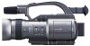 |
View all JVC GY-DV300REM manuals
Add to My Manuals
Save this manual to your list of manuals |
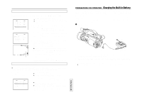
Page 27 highlights
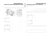
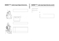
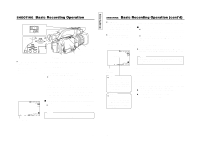
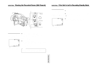
TENTATIVE SETTINGS BEFORE SHOOTING Audio Input Signal Selection The GY-DV300 is provided with three sources for audio input (i.e., built-in microphone and input connectors MIC 1 and MIC 2 for external microphones). Two channels of sound can be recorded on the tape in digital PCM format. Select for each channel (CH1 and CH2) which sound should be recorded on the channel. The sound of each of the input sources is monaural. MIC 1 Built-in microphone input connector Select whether the built-in microphone or a microphone connected to the MIC 1 input connector should be used. MIC 2 input connector The built-in microphone and a microphone connected to the MIC 1 input connector cannot be used at the same time. When using the GY-DV300 with the built-in microphone or a microphone connected to the MIC 1 input connector, select which one to use by setting the MIC1 INPUT SEL item on the SYSTEM [1/2] menu screen. SYSTEM [1/2] menu screen SY STEM [ 1 / 2 ] M I C1 I NPUT SE L I NT WI N D CUT M I C1 OF F W I N D C UT M I C 2 OF F +48V M IC1 OF F +48V M IC2 OF F AUD I O MOD E 4 8K REC MODE SP LONG PAUSE T I ME 3 0 M I N N E X T P AG E PAGE BACK Ⅲ Set to INT to use the built-in microphone. Ⅲ Set to MIC 1 to use the microphone connected to the XLR input connector. POWER OFF ON MODE CAM-B CAM-A VTR GAIN SHUTTER PUSH BAR AW MENU FWD REV CH-1 AUDIO CH-2 MIC1 MIC2 MONITOR CH-1 CH-2 MIX CH-1 AUDIO CH-2 MIC1 MIC2 AUDIO input signal selector switch Select the input signal to the CH-1, CH-2 audio channels The audio signal input to the CH-1, CH-2 audio channels is selected with the AUDIO input selector switch. The input can be set separately for each channel. Setting MIC 1 Input Signal The microphone sound from the built-in microphone or a microphone connected to the MIC 1 input connector. (Make the selection with the MIC1 INPUT SEL item on the SYSTEM [1/2] menu screen.) MIC 2 The microphone sound from a microphone connected to the MIC 2 input connector. The same sound can be input to both the CH-1 and CH-2 channels. SETTINGS BEFORE SHOOTING Audio Input Signal Selection (cont'd) Setting Whether Phantom Microphone Should be used as External Microphone SYSTEM [1/2] menu screen SY STEM [ 1 / 2 ] M I C1 I NPUT SE L XL R WI N D CUT M I C1 OF F W I N D C UT M I C 2 OF F +48V M IC1 ON +48V M IC2 ON AUD I O MOD E 4 8K REC MODE SP LONG PAUSE T I ME 30M I N N E X T P AG E PAGE BACK When a microphone (phantom microphone) requiring +48V DC power supply is connected, set the +48V MIC1 or +48V MIC2 items on the SYSTEM [1/2] menu screen. +48V MIC1 : Setting for the microphone connected to the MIC 1 input connector. +48V MIC2 : Setting for the microphone connected to the MIC 2 input connector. ● Set to ON when a phantom microphone is used. ● Set to OFF when other microphone type than phantom microphone is used. CAUTION: ● Confirm that the +48V MIC1 or +48V MIC2 items are set to OFF before connecting another microphone type than phantom microphone. ● When the setting of the +48V MIC1/MIC2 item is changed, noise will appear in the sound but this is normal. 49 50
-
 1
1 -
2
-
3
-
4
-
5
-
6
-
7
-
8
-
9
-
10
-
11
-
12
-
13
-
14
-
15
-
16
-
17
-
18
-
19
-
20
-
21
-
 22
22 -
 23
23 -
 24
24 -
 25
25 -
 26
26 -
 27
27 -
 28
28 -
 29
29 -
 30
30 -
 31
31 -
 32
32 -
33
-
34
-
35
-
36
-
37
-
38
-
39
-
40
-
41
-
42
-
43
-
44
-
45
-
46
-
47
-
48
-
49
-
50
-
51
-
52
-
53
-
54
-
55
-
56
-
57
 |
 |
