JVC GY-DV300REM Instruction Manual - Page 46
MENU Screen Structure (VTR Play- back/ DV Signal Input (U MODEL) Mode), Setting Menu Screens
 |
View all JVC GY-DV300REM manuals
Add to My Manuals
Save this manual to your list of manuals |
Page 46 highlights
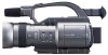
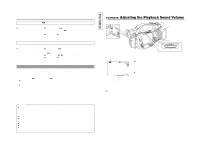
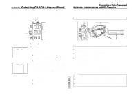
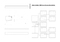
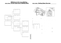
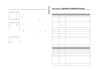
MENU Screen Structure (VTR PlayMENU SCREEN back/DV Signal Input (U MODEL) Mode) The following shows the MENU screen structure when the MODE switch on the rear section is set to "VTR". VTR menu screen V TR PB AUD I O SELECT CH1 / 2 REM F F / REW MO DE F F / REW P AG E BAC K D RUM HOUR 000200 TOP MENU screen MENU VTR SET . . SY ST EM S ET . . D I S PL AY SET . . C L OC K / T C . . MENU AL L RESE T EX I T CANCE L Normal screen SYSTEM menu screen SY STEM REC MOD E S P (U MODEL) LONG PAUS E T I ME 3 0M I N TA L LY ON (U MODEL) N E T R EMOT E ON S E T UP O F F (U MODEL) PAGE BACK DISPLAY [1/2] menu screen D I SPLAY [ 1 / 2 ] Z EBR A OFF L CD BR I GHT NE S S NORMAL LCD CO LOR NORMA L LCD PEAK I NG NORMA L V F BR I GHT NESS NORMAL VF COLOR NORMA L V F PEAK I NG NORMA L NEXT P AGE P AGE B ACK CLOCK/TC menu screen C LOCK / TC TC PRESET . . CLOCK ADJ US T . . DATE STYLE MM / DD / Y Y T I ME STYLE 2 4 HOUR SEC D I S PL AY ON P AG E BAC K DISPLAY [2/2] menu screen D I SPLAY [ 2 / 2 ] TAPE REMA I N ON T I ME CODE ON T I ME/ DATE D I SPLAY DI S P STYLE DATE + T I ME AUD I O LE V EL ON OUT PU T CHAR . MI X P AGE BACK Screen for presetting time code T C PRESET TC 0 0:00 : 00: 00 CL E AR CANCE L P AGE BACK Screen for setting date and time CL OCK ADJ UST D A T E ( MM / DD / Y Y ) 0 1 / 0 1 / 0 1 T I ME 00 :00 PAGE BACK 87 TENTATIVE MENU SCREEN Setting Menu Screens Various settings are made on the menu screens in accordance with the mode of usage of the GY-DV300. In the shooting mode, settings can be made on two separate sets of menus in accordance with the setting of the MODE switch ("CAM-A" or "CAM-B"). The contents of settings are retained in the GYDV300's memory also when the power is turned off. POWER switch MODE switch POWER OFF ON MENU button MODE CAM-B CAM-A VTR GAIN SHUTTER MENU SELECT dial ● Menus cannot be set during a recording. In the shooting mode, the MODE item on the TOP MENU screen is used to decide whether the AUTO mode or MANUAL mode should be used. TOP menu screen MENU MO D E MANU AL E A R PHON E LEV EL 1 0 S YS T EM S E T . . D I S PLAY SE T . . CAME RA S E T [ C AM - A ] . . OPER AT I ON [ CAM- A ] . . C LOC K / TC . . MENU A L L R ESE T CANCE L EX I T Cursor Indicates position of MODE switch Ⅲ Make the settings while observing the LCD screen or the viewfinder screen. If the OUTPUT CHAR. item on the DISPLAY [2/2] screen is set to MIX, the menu screen can also be viewed on a monitor connected to theVIDEO OUT orY/C OUT connector. 1. Set the POWER switch to "ON". 2. Set the MODE switch. ("CAM-A", "CAM-B", "VTR") 3. Press the MENU button for about 1 second. ● The TOP MENU screen appears. 4. Select the menu screen to be set. Rotate the SELECT dial to align the cursor (f) with the menu screen to be set, and then press the SELECT dial. ● The selected menu screen appears. 5. Select the menu item on the menu screen. Rotate the SELECT dial to align the cursor (f) with the menu item to be set, and then press the SELECT dial. ● The setting area of the selected item starts blinking, and the desired value can now be set. 88
-
 1
1 -
2
-
3
-
4
-
5
-
6
-
7
-
8
-
9
-
10
-
11
-
12
-
13
-
14
-
15
-
16
-
17
-
18
-
19
-
20
-
21
-
22
-
23
-
24
-
25
-
26
-
27
-
28
-
29
-
30
-
31
-
32
-
33
-
34
-
35
-
36
-
37
-
38
-
39
-
40
-
 41
41 -
 42
42 -
 43
43 -
 44
44 -
 45
45 -
 46
46 -
 47
47 -
 48
48 -
 49
49 -
 50
50 -
 51
51 -
52
-
53
-
54
-
55
-
56
-
57
 |
 |
