Lexmark E460 IPDS Emulation User's Guide - Page 38
Descriptions of IPDS Bin Selection Numbers, 3.6.3 Default Bin Mapping
 |
View all Lexmark E460 manuals
Add to My Manuals
Save this manual to your list of manuals |
Page 38 highlights
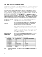
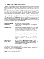
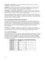
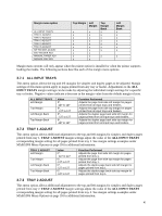
Output Bin 1 - Output Bin 10 - Selects additional standard output bins available on the printer or optional physical output bins when installed. Fin High Cap - Selects the optional finisher output bin with the highest capacity. The order of option installation does not affect the physical bin associated with the Fin High Cap bin value. This value is always associated with the highest capacity physical bin of the optional finisher. Bin Mapping 12 = Fin High Cap = IPDS number 25 is a default value on all printers. Assuming the optional finisher is installed and this default value is not changed, jobs that select IPDS bin number 25 on the host will always be routed to the finisher bin with the highest capacity. When hole punching is available in a physical bin, bin selection values may be followed by 'Hp' which indicates hole punching is available. Examples are: Output Bin 1 Hp, Output Bin 2 Hp, Fin High Cap Hp. When a value with 'Hp' is selected, all pages in an IPDS job routed to this bin are hole punched. See Hole Punching on page 61 for additional information. 3.6.2 Descriptions of IPDS Bin Selection Numbers Host applications select printer physical bins by sending IPDS bin selection numbers ranging from 1 to 255. These IPDS bin numbers may be mapped to any physical bin on the printer by changing the printer physical bin selected by the IPDS bin selection number. Assuming printer default output bin mapping, when IPDS number 1 is received in an IPDS job, the pages are routed to the printer Standard Bin. When IPDS bin selection number 2 is received in an IPDS job, the pages are routed to the second printer physical output bin. Bin Mapping 12 = Fin High Cap = IPDS bin selection number 25, is a default value on all printers. Assuming the optional finisher is installed and this default value is not changed, jobs that select IPDS bin selection number 25 on the host will always be routed to the finisher bin with the highest capacity. 3.6.3 Default Bin Mapping The default bin mapping shown below represents a typical relationship between IPDS output bin selection numbers and the printer physical output bins. The default mapping when optional output bins are installed on the printer is shown in the table below for all printers. In the table below, the labels Bin Mapping 1Bin Mapping 12 refer to the number of the mapping, not the printer physical output bin. All printers do not support ten optional output bins or an optional finisher. Default settings will be assigned for all output bins available on your printer. Bin Mapping No. Æ Bin Mapping 1 Bin Mapping 2 Bin Mapping 3 Bin Mapping 4 Bin Mapping 5 Bin Mapping 6 Bin Mapping 7 Bin Mapping 8 Bin Mapping 9 Bin Mapping 10 Bin Mapping 11 Bin Mapping 12 Output Bin Value Æ IPDS (Bin Selection) Number Standard Bin 1 Bin 1 2 Bin 2 3 Bin 3 4 Bin 4 5 Bin 5 6 Bin 6 7 Bin 7 8 Bin 8 9 Bin 9 10 Bin 10 11 Fin High Cap 25 38
-
 1
1 -
2
-
3
-
4
-
5
-
6
-
7
-
8
-
9
-
10
-
11
-
12
-
13
-
14
-
15
-
16
-
17
-
18
-
19
-
20
-
21
-
22
-
23
-
24
-
25
-
26
-
27
-
28
-
29
-
30
-
31
-
32
-
 33
33 -
 34
34 -
 35
35 -
 36
36 -
 37
37 -
 38
38 -
 39
39 -
 40
40 -
 41
41 -
 42
42 -
 43
43 -
44
-
45
-
46
-
47
-
48
-
49
-
50
-
51
-
52
-
53
-
54
-
55
-
56
-
57
-
58
-
59
-
60
-
61
-
62
-
63
-
64
-
65
-
66
-
67
-
68
-
69
-
70
-
71
-
72
-
73
-
74
-
75
-
76
-
77
-
78
-
79
-
80
-
81
-
82
-
83
-
84
-
85
-
86
-
87
-
88
-
89
-
90
-
91
-
92
-
93
-
94
-
95
-
96
-
97
-
98
-
99
-
100
-
101
-
102
-
103
-
104
-
105
-
106
-
107
-
108
-
109
-
110
-
111
-
112
-
113
-
114
-
115
-
116
-
117
-
118
-
119
 |
 |