Marantz SR5002 SR4002_Rear_Panel_Drawing - Page 23
Connecting Video Components
 |
View all Marantz SR5002 manuals
Add to My Manuals
Save this manual to your list of manuals |
Page 23 highlights
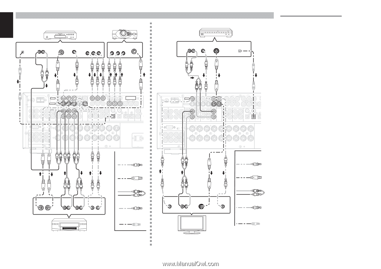
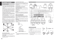
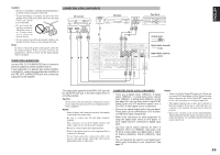
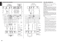
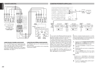
ENGLISH CONNECTING VIDEO COMPONENTS DVD player VIDEO PROJECTOR DIGITAL OUT AUDIO OUT LR S-VIDEO VIDEO OUT OUT COMPONENT VIDEO OUT Y CB / PB CR / PR COMPONENT S-VIDEO VIDEO IN IN Y CB / PB CR / PR LR VIDEO FM (75) GND AM ANTENNA L SL C L S-VIDEO TV SBL INPUT 1 DVD VCR IN VCR OUT DSS INPUT MONITOR OUT 2 Y COMPONENT INPUT 3 VIDEO MONITOR 1 OUT 2 CB/PB CR/PR Y CB/PB CR/PR Y CB/PB CR/PR IN 4 5 R R SR SW (AUX2) 7.1CH INPUT SBR MULTI. OUT TV RS-232C SPEAKER C OFF ON DVD IN OUT VCR DSS IN OUT TAPE AUDIO 1 IN OUT CD/CDR 2 3 DIGITAL IN OPT OUT DIGITAL OUT REMOTE CONT. FLASHER IN L SL C SBL R L R L R L R L FRONT B FRONT A SURROUND BACK SURROUND CENTER R SR SW SBR FRONT A OR B.CENTER. FRONT A + B : 8 OHMS PRE OUT SPEAKER C/MULTI SPEAKER SURR.SURR BACK : 6-8 OHMS SPEAKER SYSTEMS SWITCHED 1.25A 150W AC OUTLETS 120V 60Hz LR LR RL Video LR LR S-VIDEO Analog Audio S-VIDEO OUT IN AUDIO AUDIO VIDEO OUT IN OUT IN L R LR VCR Digital Audio (coaxial) Digital Audio (optical) LR LR Satellite Tuner AUDIO VIDEO S-VIDEO OUT OUT OUT LR LR DIGITAL OUT RL VIDEO INPUT 1 COMPONENT INPUT 3 VIDEO FM (75) GND AM S-VIDEO 1 ANTENNA INPUT TV DVD VCR IN VCR OUT DSS MONITOR OUT 2 Y CB/PB CR/PR Y CB/PB CR/PR Y L SL C SBL 4 5 L R R SR SW (AUX2) 7.1CH INPUT SBR MULTI. OUT TV RS-232C SPEAKER C OFF ON DVD IN OUT VCR DSS IN OUT TAPE AUDIO 1 IN OUT CD/CDR 2 3 DIGITAL IN L SL C SBL R L R L R L R L FRONT B FRONT A SURROUND BACK SURROUND CENTER R SR SW SBR FRONT A OR B.CENTER. FRONT A + B : 8 OHMS PRE OUT SPEAKER C/MULTI SPEAKER SURR.SURR BACK : 6-8 OHMS SPEAKER SYSTEMS LR LR VIDEO AUDIO OUT OUT S-VIDEO IN LR Video S-VIDEO Analog Audio VIDEO IN Digital Audio (coaxial) Digital Audio (optical) VIDEO, S-VIDEO , COMPONENT JACKS There are 3 types of video jacks on the rear panel. VIDEO jack The video signal for the VIDEO jacks is the conventional composite video signal. S-VIDEO jack The video signal is separated into luminance (Y) and color (C) signals for the S-VIDEO jack. The S-VIDEO signals enables high-quality color reproduction. If your video component has an S-VIDEO output, we recommend to use it. Connect the S-VIDEO output jack on your video component to the S-VIDEO input jack on this unit. Component jack Make component video connections to a TV or monitor with component inputs to produce higher quality video images. Use a component video cable or 3 video cords to connect the component video out jacks on the unit to the monitor. Notes: • Be sure to connect the left and right audio channels properly. Red connectors are for the R (right) channel, and white connectors are the for L (left) channel. • Be sure to connect the inputs and outputs of the video signals properly. • This unit has the "TV-AUTO ON/OFF" function to turn the TV ON or OFF automatically, by sensing the incoming video signal from the VIDEO jacks. • You may need to setup the digital audio output format of your DVD player, or other digital source components. Refer to the instructions of the each component connected to the digital input jacks. • There is no Dolby Digital RF input jack. Use an external RF demodulator with a Dolby Digital decoder to connect the Dolby Digital RF output jack of the DVD player to the digital input jack on this unit. • The COMPONENT OUTPUT 1 and 2 terminals of the SR5002 can output the same video signal. • For details concerning the connection of Video equipment, please see VIDEO CONVERT (page 35). TV 20
-
 1
1 -
2
-
3
-
4
-
5
-
6
-
7
-
8
-
9
-
10
-
11
-
12
-
13
-
14
-
15
-
16
-
17
-
 18
18 -
 19
19 -
 20
20 -
 21
21 -
 22
22 -
 23
23 -
 24
24 -
 25
25 -
 26
26 -
 27
27 -
 28
28 -
29
-
30
-
31
-
32
-
33
-
34
-
35
-
36
-
37
-
38
-
39
-
40
-
41
-
42
-
43
-
44
-
45
-
46
-
47
-
48
-
49
-
50
-
51
-
52
-
53
-
54
-
55
-
56
-
57
-
58
-
59
-
60
 |
 |