Nokia IP1260 Installation Guide
Nokia IP1260 - Security Appliance Manual
 |
View all Nokia IP1260 manuals
Add to My Manuals
Save this manual to your list of manuals |
Nokia IP1260 manual content summary:
- Nokia IP1260 | Installation Guide - Page 1
Nokia IP1200 Series Security Platform Installation Guide Part No. N450897003 Rev B Published May 2004 - Nokia IP1260 | Installation Guide - Page 2
and hardware is provided by Nokia Inc. goods or services; loss of Nokia is a registered trademark of Nokia Corporation. Other products mentioned in this document are trademarks or registered trademarks of their respective holders. 040113 2 Nokia IP1200 Series Security Platform Installation Guide - Nokia IP1260 | Installation Guide - Page 3
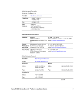
.nokia.com/ Email: Americas Voice: Fax: [email protected] Europe 1-888-361-5030 or 1-613-271-6721 Voice: 1-613-271-8782 Fax: Asia-Pacific Voice: Fax: +65-67232999 +65-67232897 +44 (0) 125-286-8900 +44 (0) 125-286-5666 031014 Nokia IP1200 Series Security Platform Installation Guide - Nokia IP1260 | Installation Guide - Page 4
4 Nokia IP1200 Series Security Platform Installation Guide - Nokia IP1260 | Installation Guide - Page 5
Hard Disk Drives 29 Disk Mirroring 29 Hard-Disk Drive Hot Swap Feature 30 Hard-Disk Drive LEDs 30 Power Supplies and Fan Unit 32 Power Supplies 33 Fan Unit 35 Site Requirements, Warnings, and Cautions 36 Software Requirements 37 Nokia IP1200 Series Security Platform Installation Guide 5 - Nokia IP1260 | Installation Guide - Page 6
and Turning the Power On 42 Performing the Initial Configuration 44 Connecting Network Interfaces 46 Using Nokia Network Voyager to Manage Your Security Platform 47 Accessing Nokia Network Voyager Reference Information. . . . . 48 Nokia Network Voyager Reference Guide 49 Nokia Network Voyager - Nokia IP1260 | Installation Guide - Page 7
. . . . 80 Dual-Port Copper Gigabit Ethernet NIC 80 Performance Considerations 80 Copper Gigabit Ethernet NIC Features 81 Dual-Port Copper Gigabit Ethernet NIC Connectors and Cables 82 Single 105 Other commands 106 halt 106 Nokia IP1200 Series Security Platform Installation Guide 7 - Nokia IP1260 | Installation Guide - Page 8
to Use Hardware Acceleration 139 Installing a Fan Unit 140 Before You Begin 140 Installing or Replacing a Power Supply 141 Before You Begin 143 Monitoring the Nokia IP1200 Series Security Platform Power Supply 144 A Technical Specifications 145 Space Requirements 146 8 Nokia IP1200 Series - Nokia IP1260 | Installation Guide - Page 9
B Compliance Information 147 Declaration of Conformity 148 Compliance Statements 150 FCC Notice (US 151 Equipment Attachment Regulations (Canada 152 Index 153 Nokia IP1200 Series Security Platform Installation Guide 9 - Nokia IP1260 | Installation Guide - Page 10
10 Nokia IP1200 Series Security Platform Installation Guide - Nokia IP1260 | Installation Guide - Page 11
Disk Drive Front Panel 31 Figure 7 Power Supply and Fan Unit Locations 33 Figure 8 Power Supply, Cooling Fan, and Power Switch Locations 34 Figure 9 Power Switch Location 42 Figure 10 Nokia Cable Connector Output Pin Assignments . . 84 Nokia IP1200 Series Security Platform Installation Guide 11 - Nokia IP1260 | Installation Guide - Page 12
96 Figure 29 E1 Network Interface Card Receptacle and Pin Assignments 98 Figure 30 E1 Crossover Cable Connection Diagram 98 Figure 31 Location of Hard Disk Drives 120 Figure 32 DIMM Socket Locations 129 12 Nokia IP1200 Series Security Platform Installation Guide - Nokia IP1260 | Installation Guide - Page 13
Series Security Platform Specifics 20 Table 3 PMC Expansion Slots 25 Table 4 System Status LEDs 28 Table 5 Hard-Disk Drive LEDs 31 Table 6 Power Supply Status LEDs 34 Table 7 NIC PCI Frequency 72 Table 8 Boot Manager Variables 98 Nokia IP1200 Series Security Platform Installation Guide 13 - Nokia IP1260 | Installation Guide - Page 14
14 Nokia IP1200 Series Security Platform Installation Guide - Nokia IP1260 | Installation Guide - Page 15
Guide This manual provides information for the installation and use of the Nokia IP1200 Series Security Platforms. Installation and maintenance should be performed by experienced technicians or Nokia-approved service providers only. This preface provides the following information: „ In This Guide - Nokia IP1260 | Installation Guide - Page 16
„ Chapter 7, "Troubleshooting" discusses problems you might encounter and proposes solutions to these problems. „ Chapter 8, "Installing and Replacing Other Components" describes how to install or replace memory, hard disk drives, and power supplies. „ Appendix A, "Technical Specifications" provides - Nokia IP1260 | Installation Guide - Page 17
key when an instruction says type. • Emphasizes a point or denotes new terms at the place where they are defined in the text. • Indicates an external book title reference. • Indicates a variable in a command: delete interface if_name Nokia IP1200 Series Security Platform Installation Guide 17 - Nokia IP1260 | Installation Guide - Page 18
inline help for a specific subject, click Help next to the subject. To access the Nokia Network Voyager Reference Guide for tasks, examples, and more information, click Doc. Check Point documentation is available from the Check Point Web site at www.checkpoint.com. 18 Nokia IP1200 Series Security - Nokia IP1260 | Installation Guide - Page 19
Cautions „ Software Requirements About the Nokia IP1200 Series Security Platform The Nokia IP1200 Series Security Platform combines the power of the Nokia IPSO operating system with the Nokia Secure Access System and firewall applications. The Nokia IP1260 Security Platform is a high-end, multi port - Nokia IP1260 | Installation Guide - Page 20
1 Overview Table 2 Nokia IP1200 Series Security Platform Specifics IP Security Platform IPSO Version Software Initial Memory Upgradeable Configuration RAM IP1260 v3.7 or later Check Point NG FP3 (hf2) Nokia Secure Access System v1.02 or later 1 GB 2 GB IP1220 v3.8 or later Check Point NG - Nokia IP1260 | Installation Guide - Page 21
Your Security Platform" on page 47. „ The IPSO command-line interface (CLI)-an SSHv2-secured interface that enables you to easily configure Nokia IP security platforms from the command line. Everything that you can accomplish with Network Nokia IP1200 Series Security Platform Installation Guide 21 - Nokia IP1260 | Installation Guide - Page 22
Horizon Manager, you can securely install and upgrade the Nokia proprietary IPSO operating system, plus hardware and third-party applications such as Check Point VPN-1/FireWall-1 for Nokia. Horizon Manager can perform installations and upgrades on up to 2,500 Nokia IP security platforms, offering - Nokia IP1260 | Installation Guide - Page 23
. Figure 1 Component Locations Front View System status LEDs Dual 6U PMC carrier expansion slots 1 and 2 Hard disk drive A Hard disk drive B 00307a.1 Console port Serial (AUX) port PCMCIA slots Ethernet management ports (slot 3) Nokia IP1200 Series Security Platform Installation Guide 23 - Nokia IP1260 | Installation Guide - Page 24
local country approval for Nokia T1, E1, ISDN, or other NICs. Refer to your reseller or distributor to determine if these NICs are approved for the desired country. Specific NICs might not be available for use in a particular country. 24 Nokia IP1200 Series Security Platform Installation Guide - Nokia IP1260 | Installation Guide - Page 25
-Port T1 NIC" on page 91 Note Nokia products only support NICs purchased from Nokia or Nokiaapproved resellers. The Nokia Global Support Services group can only provide support for Nokia products that use Nokia-approved accessories. Nokia IP1200 Series Security Platform Installation Guide 25 - Nokia IP1260 | Installation Guide - Page 26
a Nokia service provider listed in the "Nokia Contact Information" on page 3. Console Port Use the built-in console port, shown in Figure 1, to supply information 5 GND Output 6 DSR Input 7 RTS Output 8 CTS 9 DTR Input Output 26 Nokia IP1200 Series Security Platform Installation Guide - Nokia IP1260 | Installation Guide - Page 27
Nokia IP1200 Series Security Platform Overview Serial (AUX) Port Use the built-in serial (AUX) port, shown in 4 (RTS) 5 (CTS) 22 (RI) To DB9 Cable Out 7 (RTS) 8 (CTS) 3 (TXD) 2 (RXD 6 (DSR) 9 (RI) 5 (GND) 4 (DTR) 1 (DCD) 1 (DCD) 4 (DTR) Nokia IP1200 Series Security Platform Installation Guide 27 - Nokia IP1260 | Installation Guide - Page 28
Fault Table 4 shows the system status LEDs and describes their meaning. Table 4 System Status LEDs Status Indicator Meaning Symbol Solid blue Power on Solid yellow Appliance is experiencing an internal voltage problem. ! 28 Nokia IP1200 Series Security Platform Installation Guide - Nokia IP1260 | Installation Guide - Page 29
IP1260 comes with two hard disk drives as the standard package. The IP1220 comes with one hard disk drive; a second one is optional. The hard disk drives support hot swapping, and an optional disk-mirroring feature, described in the following section. Disk Mirroring The Nokia disk-mirroring feature - Nokia IP1260 | Installation Guide - Page 30
. For more information about disk mirroring, including configuration details, see the Nokia Network Voyager Reference Guide and the IPSO Release Notes and Getting Started Guide for the version of IPSO you are running. Hard-Disk Drive Hot Swap Feature If you configure disk mirroring, you can use - Nokia IP1260 | Installation Guide - Page 31
Hot swap button 00319 Caution To avoid damage to the ejection lever, loosen the two retaining screws before you remove the hard disk drive. Once screw is located behind the ejection lever, and the other screw is on the opposite side. Nokia IP1200 Series Security Platform Installation Guide 31 - Nokia IP1260 | Installation Guide - Page 32
is testing the hard disk drive. Note Do not remove the hard disk drive if the Status LED is blinking green. Power Supplies and Fan Unit The power supplies and fan unit are located at the rear of the IP1200 Series, as shown in Figure 7. 32 Nokia IP1200 Series Security Platform Installation Guide - Nokia IP1260 | Installation Guide - Page 33
redundancy. The IP1260 comes with two power supplies as the standard package. The IP1220 comes with power supply; a second one is optional. The power supplies are hot swappable and perform load sharing while two active power supplies are installed, increasing the life of the power supplies. Note On - Nokia IP1260 | Installation Guide - Page 34
how to install or remove and replace a failed power supply, see "Installing or Replacing a Power Supply" on page 141. Power Supply Status LEDs The power supply status LEDs provide the status of the power supplies as described in Table 6. 34 Nokia IP1200 Series Security Platform Installation Guide - Nokia IP1260 | Installation Guide - Page 35
Nokia IP1200 Series Security Platform Overview Table 6 Power Supply Status LEDs LED LED status Meaning Fault Red Power supply has a voltage problem and power was turned off. or One power supply in a redundant system is not turned on. Over Temp Yellow Power supply has an internal - Nokia IP1260 | Installation Guide - Page 36
type battery recommended by the manufacturer. Dispose of used batteries according to the manufacturer's instructions. Caution Do not block any of the ventilation holes on the appliance. The components might overheat and become damaged. 36 Nokia IP1200 Series Security Platform Installation Guide - Nokia IP1260 | Installation Guide - Page 37
Nokia IP1260 Security Platform supports the following operating system and applications as of the publication date for this guide: „ Nokia operating system software requirements-IPSO v3.7 or later. „ Firewall and VPN software requirements-Check Point NG FP3 (hf2) VPN-1/FireWall-1 or later. „ Nokia - Nokia IP1260 | Installation Guide - Page 38
1 Overview 38 Nokia IP1200 Series Security Platform Installation Guide - Nokia IP1260 | Installation Guide - Page 39
how to perform the initial configuration manually by using a console connection. It includes the following sections: „ Using a Console Connection „ Connecting Power and Turning the Power On „ Performing the Initial Configuration „ Connecting Network Interfaces „ Accessing Nokia Network Voyager - Nokia IP1260 | Installation Guide - Page 40
the Initial Configuration Note Nokia recommends that you physically install all NICs and other hardware components before you perform the initial configuration procedure this chapter describes. For information about how to install NICs, see Chapter 4, "Installing and Replacing Network Interface - Nokia IP1260 | Installation Guide - Page 41
-through cable. 00307a.1 Console port For cable pin assignments for the console connection, see "Console Port" on page 26. 2. Connect the other end of the cable to the VT100 console or to a system running a terminal-emulation program. Nokia IP1200 Series Security Platform Installation Guide 41 - Nokia IP1260 | Installation Guide - Page 42
into the power cord receptacle on the power supply. 2. Plug the other end of the power cord into a three wire grounded power strip or wall outlet. 3. Toggle the 1/O power switch to the 1 position to provide power to the IP1200 Series. 42 Nokia IP1200 Series Security Platform Installation Guide - Nokia IP1260 | Installation Guide - Page 43
Nokia service provider or Nokia Support as listed in "Nokia Contact Information" on page 3 for technical support. Note On an appliance with two active power supplies installed, connect and turn on both power supplies for load sharing and redundancy. If two power supplies are installed and both power - Nokia IP1260 | Installation Guide - Page 44
ensure that the serial cable is completely plugged in at both ends. If you verify the console connections and still do not see the settings are correct, contact your Nokia service provider as listed in "Nokia Contact Information" on page 3. 2. Nokia IP1200 Series Security Platform Installation Guide - Nokia IP1260 | Installation Guide - Page 45
Performing the Initial Configuration on your network is Nokia recommends that you select one of the Ethernet management interface ports. To select an interface, enter the number adjacent to the physical ID in the list of connected interfaces. Nokia IP1200 Series Security Platform Installation Guide - Nokia IP1260 | Installation Guide - Page 46
." You can also connect the remaining LAN and WAN interface cables at this point, although you are not required to do so. Note Nokia recommends that you use one of the four front-panel Ethernet management ports for this connection. 46 Nokia IP1200 Series Security Platform Installation Guide - Nokia IP1260 | Installation Guide - Page 47
To open Nokia Network Voyager 1. Start a Web browser on the host you plan to use to configure or monitor your appliance. 2. In the Location or Address field, enter the IP address of the initial interface you configured for the appliance. Nokia IP1200 Series Security Platform Installation Guide 47 - Nokia IP1260 | Installation Guide - Page 48
have a network routing problem. Confirm the information you entered during the initial configuration and check that all cables are firmly connected. For more information, see the troubleshooting chapter in the appropriate installation guide. Accessing Nokia Network Voyager Reference Information - Nokia IP1260 | Installation Guide - Page 49
reference source for Voyager. To access this source, click Doc. You can also access the Nokia Network Voyager Reference Guide and other Nokia IPSO documentation at the Nokia support site (https:// support.nokia.com) or on the software CD that was delivered with your appliance (see the doc folder - Nokia IP1260 | Installation Guide - Page 50
your admin username and password. 3. Enter clish to access the CLI. For further information about establishing a connection with and invoking the CLI, see the Nokia CLI Reference Guide for IPSO-SX for the version of IPSO-SX you are using. 50 Nokia IP1200 Series Security Platform Installation Guide - Nokia IP1260 | Installation Guide - Page 51
Manager Using Nokia Horizon Manager You can use Horizon Manager to install and upgrade the Nokia proprietary Nokia IPSO operating system. For information about how to obtain Horizon Manager, see the "Nokia Contact Information" on page 3. Nokia IP1200 Series Security Platform Installation Guide 51 - Nokia IP1260 | Installation Guide - Page 52
2 Performing the Initial Configuration 52 Nokia IP1200 Series Security Platform Installation Guide - Nokia IP1260 | Installation Guide - Page 53
you are properly grounded before you touch any electronic component. Rack Mounting the Security Platform The Nokia IP1200 Series Security Platform mounts in a standard 19-inch equipment rack with four mounting screws, as Figure 11 shows. Nokia IP1200 Series Security Platform Installation Guide 53 - Nokia IP1260 | Installation Guide - Page 54
3 Installing the Nokia IP1200 Series Security Platform Figure 11 Rack-Mounting Screw Locations 00307a.1 Rack-mounting screw the grounding lugs provided. The grounding lugs provide a grounding attachment point for NEBS compliance. 54 Nokia IP1200 Series Security Platform Installation Guide - Nokia IP1260 | Installation Guide - Page 55
nut onto the stud. Do not over tighten the nuts. 6. Attach the grounding cable to an earth ground or other grounding point to meet the specifications of your installation site. Nokia IP1200 Series Security Platform Installation Guide 55 - Nokia IP1260 | Installation Guide - Page 56
3 Installing the Nokia IP1200 Series Security Platform To rack mount the security platform Caution The security platform is heavy. Use the IP1200 Series. Fan unit 00308a b. Loosen the retaining screws by turning them counterclockwise. 56 Nokia IP1200 Series Security Platform Installation Guide - Nokia IP1260 | Installation Guide - Page 57
remove the power supplies from the rear of the appliance. a. Locate the power supply on the back of the IP1200 Series and the two screws that secure it. Power supplies b. Remove the two retaining screws. c. Remove the grounding lugs. Nokia IP1200 Series Security Platform Installation Guide 00308a - Nokia IP1260 | Installation Guide - Page 58
following the instructions provided with the wrist strap before you handle the components or open the appliance. If you do not have a grounding wrist strap, make sure you are properly grounded before you touch any electronic component. 58 Nokia IP1200 Series Security Platform Installation Guide - Nokia IP1260 | Installation Guide - Page 59
out of the appliance. 00326a.1 c. Place the chassis assembly on a properly grounded surface. 5. Adjust the mounting brackets on the side of the appliance if necessary. Nokia IP1200 Series Security Platform Installation Guide 59 - Nokia IP1260 | Installation Guide - Page 60
3 Installing the Nokia IP1200 Series Security Platform 6. Mount the appliance into a standard 19-inch rack by using the assembly retaining screws. 8. Reinstall the fan unit into the rear of the appliance. 9. Reinstall the power supplies. 60 Nokia IP1200 Series Security Platform Installation Guide - Nokia IP1260 | Installation Guide - Page 61
Series supports the following NICs: „ Four-port and dual-port 10/100 Ethernet „ Dual-port fiber-optic Gigabit Ethernet „ Dual-port copper Gigabit Ethernet „ Single-port ISDN S/T „ Single-port V.35 or X.21 „ Single-port T1 „ Single-port E1 Nokia IP1200 Series Security Platform Installation Guide 61 - Nokia IP1260 | Installation Guide - Page 62
slots on the front of the appliance that hold two 6U PMC carriers. All NICs installed in the IP1200 Series are housed in the 6U PMC carrier. You must first remove the 6U PMC carrier from its slot before you can remove or install a NIC. 62 Nokia IP1200 Series Security Platform Installation Guide - Nokia IP1260 | Installation Guide - Page 63
the IP1200 Series supports hot swapping of NICs, you do not have to turn off power from the system to remove, install, or replace a NIC. Before You Begin Before you install the card, make sure that the rubber gasket around the front of the card is installed properly. To remove, install, or replace - Nokia IP1260 | Installation Guide - Page 64
is extinguished when the power is removed. 4. Press or push the levers toward the outer edges of the IP1200 Series. Ejection and locking levers Push red button to disengage or engage lock IPHILO Release or lock into place 00310b.1 64 Nokia IP1200 Series Security Platform Installation Guide - Nokia IP1260 | Installation Guide - Page 65
the front panel of the IP1200 Series. 6. Gently pull the PMC carrier out from the slot and place it on a suitable, grounded work surface. 00310a.1 Nokia IP1200 Series Security Platform Installation Guide 65 - Nokia IP1260 | Installation Guide - Page 66
keep the NIC attached, on the underside of the PMC carrier. 8. Remove the two bezel retaining screws with a Phillips screwdriver. 00311 Note If you are installing a NIC in an unoccupied slot on the PMC carrier, remove the blank bezel that covers the slot and retain it for future use. Proceed to - Nokia IP1260 | Installation Guide - Page 67
10. Remove the NIC by lifting the back of the NIC away from the chassis assembly and pulling it gently away from the front panel. Nokia IP1200 Series Security Platform Installation Guide 00313 67 - Nokia IP1260 | Installation Guide - Page 68
4 Installing and Replacing Network Interface Cards 11. Insert the new NIC or a blank bezel by of the PMC carrier. Proceed to step 13. Note The blank bezel is required for the IP1200 Series to meet emissions requirements during operation. 68 Nokia IP1200 Series Security Platform Installation Guide - Nokia IP1260 | Installation Guide - Page 69
Removing, Installing, and Replacing NICs 12. From the top of the PMC carrier, screw the NIC retaining screws into the standoffs on the PMC carrier back into its original slot on the front of the IP1200 Series until it clicks into place. Nokia IP1200 Series Security Platform Installation Guide 69 - Nokia IP1260 | Installation Guide - Page 70
card carrier. The power indicator LED on the PMC carrier illuminates green. . 00315.1 If you are replacing a NIC with a new NIC of the same type, the Nokia IPSO operating system automatically recognizes the NIC and applies the original configuration to the new NIC. If you are installing a new or - Nokia IP1260 | Installation Guide - Page 71
detailed port information. For information about how to access Network Voyager, see "Accessing Nokia Network Voyager Reference Information" on page 48. You can also use the IPSO tcpdump command to examine the traffic on a specific port. Nokia IP1200 Series Security Platform Installation Guide 71 - Nokia IP1260 | Installation Guide - Page 72
4 Installing and Replacing Network Interface Cards 72 Nokia IP1200 Series Security Platform Installation Guide - Nokia IP1260 | Installation Guide - Page 73
For instructions about how to add or replace NICs, see Chapter 4, "Installing and Replacing Network Interface Cards." The NICs supported in the IP1200 Series operate at the peripheral component interconnect (PCI) frequency listed in Table 7. Nokia IP1200 Series Security Platform Installation Guide - Nokia IP1260 | Installation Guide - Page 74
your NIC installation to maximize data throughput on your appliance. Caution To protect the IP1200 Series and the memory modules instructions provided with the wrist strap before you handle the components or open the appliance. If you do 74 Nokia IP1200 Series Security Platform Installation Guide - Nokia IP1260 | Installation Guide - Page 75
to you. For information about how to add or replace a NIC, see Chapter 4, "Installing and Replacing Network Interface Cards." 10/100 Ethernet NIC Features The four-port 10/100 Ethernet NIC supports PCI operation at 100 MHz and runs on Nokia IPSO v3.8 or higher. The dual-port 10/100 Ethernet NIC - Nokia IP1260 | Installation Guide - Page 76
power is turned on and the cables are connected, the Ethernet link LEDs on both the IP1200 Series and on the remote equipment illuminate to indicate the connection. As data is transmitted, the activity LEDs on the appliance illuminate. 76 Nokia IP1200 Series Security Platform Installation Guide - Nokia IP1260 | Installation Guide - Page 77
Mbps hub or switch or to connect directly to a host. An auto-detect crossover cable feature on this NIC automatically detects the correct cable type. Use IEEE 802.3 10BASE-T, 100BASE-TX 1 2 00270 3 4 5 6 7 8 Assignment TX + TX RX + RX - Nokia IP1200 Series Security Platform Installation Guide 77 - Nokia IP1260 | Installation Guide - Page 78
to get maximum system throughput. Each 6U PMC card carrier unit has a separate PCI bus connection to the main system board. In the configuration described here, each of the two dual-port Gigabit Ethernet NIC s access a separate PCI bus. 78 Nokia IP1200 Series Security Platform Installation Guide - Nokia IP1260 | Installation Guide - Page 79
the power is turned on and the cables are connected, the Ethernet link LEDs on both the IP1200 Series and on the remote equipment illuminate to indicate the connection. As data is transmitted, the activity LEDs on the appliance illuminate. Nokia IP1200 Series Security Platform Installation Guide - Nokia IP1260 | Installation Guide - Page 80
end of the cable can be either LC or SC, depending on the type of connector required for Nokia IP1200 Series Security Platform supports Nokia-approved, dual-port copper Gigabit Ethernet NICs installed see Chapter 4, "Installing and Replacing Network Interface Cards." Performance Considerations If you - Nokia IP1260 | Installation Guide - Page 81
Performance Considerations maximum system throughput capable NIC installed. Copper Gigabit Ethernet NIC Features The copper Gigabit Ethernet NIC supports: „ High specifications „ Cable autosensing You can configure and monitor Gigabit Ethernet NIC interfaces with Nokia Network Voyager. Specifically - Nokia IP1260 | Installation Guide - Page 82
green or yellow) Activity LEDs (yellow) 1000BaseT 1 2 1 Ports 2 00386.1 \ After the power is turned on and the cables are connected, the Ethernet link LEDs on both the IP1200 Series and 26 AWG or larger telecommunication line cord. 82 Nokia IP1200 Series Security Platform Installation Guide - Nokia IP1260 | Installation Guide - Page 83
required by your network configuration). Note Certain circumstances might require shielded Category 5 Ethernet cables to meet Class B emissions requirements. Note Nokia copper Gigabit Ethernet NICs support pins facing up and toward you. Nokia IP1200 Series Security Platform Installation Guide 83 - Nokia IP1260 | Installation Guide - Page 84
3 BI_DB+ RX 4 BI_DC+ 5 BI_DC- 6 BI_DB- RX 7 BI_DD+ 8 BI_DD- To connect directly to a host, use an RJ-45 crossover cable wired as Figure 19 shows. 84 Nokia IP1200 Series Security Platform Installation Guide - Nokia IP1260 | Installation Guide - Page 85
can order appropriate adapter cables separately from a cable vendor of your choice. Single-Port ISDN S/T NIC The Nokia IP1200 Series Security Platform supports Nokia-approved, single-port ISDN S/T NICs installed on a 6U PMC carrier. When you purchase an ISDN NIC with your IP1200 Series, the NIC is - Nokia IP1260 | Installation Guide - Page 86
Note The ISDN interface is not supported for use in the USA, Canada, or Japan. Single-Port ISDN S/T NIC Features The NIC supports the following features: „ Point-to-point and multipoint NIC must be at least 26 AWG wire. NOKIA ISDN BRI 86 Nokia IP1200 Series Security Platform Installation Guide - Nokia IP1260 | Installation Guide - Page 87
the NIC to an ISDN service, use the supplied ISDN cable. Use of Nokia IP1200 Series Security Platform supports a Nokia-approved, single-port V.35 or X.21 NIC. The port type is automatically determined by the type of cable attached to the NIC. Nokia IP1200 Series Security Platform Installation Guide - Nokia IP1260 | Installation Guide - Page 88
cable. For information about how to add or replace a NIC, see Chapter 4, "Installing and Replacing Network Interface Cards." Single-Port V.35 or X.21 NIC Features The V.35 or X.21 NIC supports the following features: „ Berkeley Packet Filtering (BPF) „ Conformance with RFC 1661 (PPP), 1662 (PPP in - Nokia IP1260 | Installation Guide - Page 89
cases, you connect the NIC to a channel service unit/data service unit (CSU/DSU). If you are connecting the /DSU or other DCE device must supply the clock. On a Cisco network end and the appropriate V.35 or X.21 connector on the other end. Nokia IP1200 Series Security Platform Installation Guide 89 - Nokia IP1260 | Installation Guide - Page 90
X A Chassis Ground C Request to Send E Data Set Ready H Data Terminal Ready P Transmitted Data S Transmitted Data U Terminal Timing W Terminal Timing Y Transmit Timing AA Transmit Timing 90 Nokia IP1200 Series Security Platform Installation Guide - Nokia IP1260 | Installation Guide - Page 91
the following features: „ Built-in CSU/DSU for long and short-haul operations „ Line speed to full T1 „ High-speed access for network connections over leased lines „ On-board HDLC and Frame controllers, which allow operation at 1.544 Mbps Nokia IP1200 Series Security Platform Installation Guide 91 - Nokia IP1260 | Installation Guide - Page 92
and monitoring program for the Nokia IPSO operating system. For information about how to access Network Voyager and the related reference materials, see "Using Nokia Network Voyager to Manage Your Security Platform" on page 47. 92 Nokia IP1200 Series Security Platform Installation Guide - Nokia IP1260 | Installation Guide - Page 93
you work on any Nokia appliance. Caution Nokia requires that this equipment be installed by authorized, experienced service personnel who have the equipment installation instructions. Nokia requires that all equipment be connected to a Nokia IP1200 Series Security Platform Installation Guide 93 - Nokia IP1260 | Installation Guide - Page 94
5 Connecting PMC Network Interface Cards power source using a socket-outlet with protective grounding connection. In Figure 26 the Card Receptacle and Pin Assignments 8 1 Pin# Assignment 1 RX 2 RX 00270 3 4 TX 5 TX 6 7 8 94 Nokia IP1200 Series Security Platform Installation Guide - Nokia IP1260 | Installation Guide - Page 95
„ Up to 32 channels per card „ Channels 0 and 16 can be used for inband signaling „ IPSO supports only fractional channels „ Fractional E1 „ Support for hot-swapping of NICs when used in IP1200 Series appliances „ Tracing through tcpdump Nokia IP1200 Series Security Platform Installation Guide 95 - Nokia IP1260 | Installation Guide - Page 96
E1 interfaces by using Nokia Network Voyager, the Web-based element manager configuration and monitoring program for the Nokia IPSO operating system. For adapter cables separately from Nokia (see "Nokia Contact Information" on page 3). 96 Nokia IP1200 Series Security Platform Installation Guide - Nokia IP1260 | Installation Guide - Page 97
the E1 cable before you work on any Nokia appliance. Caution Nokia requires that this equipment be installed by authorized, experienced service personnel who have the equipment installation instructions. Nokia requires that all equipment be connected to a power source by using a socket outlet with - Nokia IP1260 | Installation Guide - Page 98
29 E1 Network Interface Card Receptacle and Pin Assignments 8 1 Pin# Assignment 1 RX 2 RX 00270 3 4 TX 5 TX 6 7 8 Figure 30 E1 Crossover Cable Connection Diagram 1 1 2 2 3 3 4 4 5 5 6 6 7 7 8 8 00018.1 98 Nokia IP1200 Series Security Platform Installation Guide - Nokia IP1260 | Installation Guide - Page 99
on nondefault devices or directories „ Installing new versions of Nokia IPSO (the operating system) „ Obtaining system information „ Performing various housekeeping tasks These tasks and boot manager maintains the default values of these Nokia IP1200 Series Security Platform Installation Guide 99 - Nokia IP1260 | Installation Guide - Page 100
nonvolatile memory. You can set and view most variables from the boot manager prompt. Table 8 lists the boot manager variables. Table 8 Boot Manager Variables Variable Description boot from which the boot-file loads. Default is wd0. 100 Nokia IP1200 Series Security Platform Installation Guide - Nokia IP1260 | Installation Guide - Page 101
syntax: printenv For example: BOOTMGR[93]> printenv NOKIA IPSO BOOTMGR VERSION=3.7 07.05.2003-130000 autoboot: YES testboot: NO bootwait: 3 boot-file: /image/current/kernel boot-flags: boot-device: wd0 vendor: Nokia model: IP bmslice: 4 Nokia IP1200 Series Security Platform Installation Guide 101 - Nokia IP1260 | Installation Guide - Page 102
the following syntax: sysinfo For example: BOOTMGR[6]> sysinfo CPU 0: 1996 MHz Pentium 4/XEON Memory: 536870912 (512M bytes) Disk Devices: IO port 0x1f0 wdc0: unit 0 (wd0): 16MB ( flags=107 102 Nokia IP1200 Series Security Platform Installation Guide - Nokia IP1260 | Installation Guide - Page 103
wd0 device. For example: BOOTMGR[2]> ls wd0 /image/current .description bootmgr etc kernel.debug usr VERSION cdrom ipso.tgz mnt web bin dev kernel sbin Setting the Variables setenv YES sets the value of autoboot to YES. Nokia IP1200 Series Security Platform Installation Guide 103 - Nokia IP1260 | Installation Guide - Page 104
name of the variable to be set to its factory default. If name is not specified, all variables are set to their factory defaults. 104 Nokia IP1200 Series Security Platform Installation Guide - Nokia IP1260 | Installation Guide - Page 105
command has the following syntax: unsetalias name where name is the name of the alias to be cleared. For example, the following command deletes the disk alias from the list of aliases: BOOTMGR[2]> unsetalias disk Nokia IP1200 Series Security Platform Installation Guide 105 - Nokia IP1260 | Installation Guide - Page 106
argument, the boot manager uses its default. It first searches its nonvolatile memory to see if the corresponding default argument is specified there. If so, it uses that value; if not, it defaults to the values in the following table: 106 Nokia IP1200 Series Security Platform Installation Guide - Nokia IP1260 | Installation Guide - Page 107
hard disk drive) /image/current/kernel -x Using the Boot Manager to Install Nokia IPSO Use the install command to install Nokia IPSO. The syntax of the command is: install For complete installation procedures, see the appropriate version of release notes. Note Using the install command to perform - Nokia IP1260 | Installation Guide - Page 108
disk on your Nokia IP1200 Series Security Platform, you can require that the user enter a password to access the boot manager install command again. Note If you forget your install password, contact the appropriate Nokia Customer Support site as listed in "Nokia Contact Information" on page 3 for - Nokia IP1260 | Installation Guide - Page 109
. If you should need to reinstall the boot manager, contact the appropriate Nokia Customer Support site as listed in "Nokia Contact Information" on page 3 for instructions and a new boot manager. The command to install the boot manager has the following syntax: install_bootmgr boot-device boot-file - Nokia IP1260 | Installation Guide - Page 110
from the appropriate Nokia Customer Support site as listed in "Nokia Contact Information" on page 3. 2. At the Nokia IPSO command prompt, disk drive (wd0). The upgrade takes some time to complete. Do not interrupt the upgrade process. 110 Nokia IP1200 Series Security Platform Installation Guide - Nokia IP1260 | Installation Guide - Page 111
reinstall the Nokia IPSO operating system onto your appliance, see Chapter 6, "Using the Boot Manager." General Troubleshooting Information The information in this section relates to problems you might encounter during the IP1200 Series installation. Appliance Not Receiving Power Problem Power cord - Nokia IP1260 | Installation Guide - Page 112
Accepted Problem Database is corrupt. Solution Return to default settings as described in "To reset the default database settings" on page 114, or contact the Nokia customer support site listed in "Nokia Contact Information" on page 3. 112 Nokia IP1200 Series Security Platform Installation Guide - Nokia IP1260 | Installation Guide - Page 113
the following command to reset the password from the command line by using a blank password: dbpasswd admin newpassword "" The two double quotation marks at the end of the command properly indicate a blank password. Nokia IP1200 Series Security Platform Installation Guide 113 - Nokia IP1260 | Installation Guide - Page 114
in Chapter 2, "Performing the Initial Configuration." To Problem The IP1200 Series is defective, or the file system on the IP1200 Series is defective. Solution Contact the Nokia customer support site listed in "Nokia Contact Information" on page 3. Note Use the full installation procedure to install - Nokia IP1260 | Installation Guide - Page 115
General Troubleshooting Information complete the full installation procedure, see the current release notes. The release notes are located on the Nokia customer support Web site as listed in the "Nokia Contact Information" on page 3. Not Able to Connect to Nokia Network Voyager Using the Ethernet - Nokia IP1260 | Installation Guide - Page 116
that the speeds match on each end of the Ethernet connection (10 Mbps, 100 Mbps, or 1000 Mbps). Problem Port not enabled. Solution Verify from the Interface page in Nokia Network Voyager that the interface port is configured as active. 116 Nokia IP1200 Series Security Platform Installation Guide - Nokia IP1260 | Installation Guide - Page 117
connections one at a time until the problem is localized to one computer and troubleshoot further. Appliance Does Not Recognize New Memory Configuration Problem The DIMMs are not properly seated in DIMM sockets. Solution Repeat memory installation procedures. Make sure DIMMs are fully seated - Nokia IP1260 | Installation Guide - Page 118
7 Troubleshooting 118 Nokia IP1200 Series Security Platform Installation Guide - Nokia IP1260 | Installation Guide - Page 119
topics are covered: „ Replacing a Hard Disk Drive „ Replacing or Upgrading Memory „ Installing a Nokia Encryption Accelerator Card „ Installing a Fan Unit „ Installing or Replacing a Power Supply „ Monitoring the Nokia IP1200 Series Security Platform Power Supply For information about how to add or - Nokia IP1260 | Installation Guide - Page 120
you touch any electronic component. Replacing a Hard Disk Drive The Nokia IP1200 Series Security Platform supports up to two hard disk drives with the disk mirroring feature in the Nokia IPSO operating system. If the appliance has only one hard disk drive installed, it is in the top slot (slot - Nokia IP1260 | Installation Guide - Page 121
when you receive it, the disk-mirroring feature is already enabled. For more information about disk mirroring, including configuration details, see the Nokia Network Voyager Reference Guide and the IPSO Release Notes and Getting Started Guide. Hard Disk Drive Hot Swap Feature A hot swap button is - Nokia IP1260 | Installation Guide - Page 122
Nokia IP1200 Series Security Platform, you can remove a failed hard disk drive without shutting down the system. You must replace the hard disk drive with a drive that has a capacity equal to or larger than the drive you are replacing. 122 Nokia IP1200 Series Security Platform Installation Guide - Nokia IP1260 | Installation Guide - Page 123
procedures, see the IPSO 3.7 Release Notes and Getting Started Guide or the Nokia Horizon Manager User Guide and online help. To replace a hard disk drive by using the hot-swap feature Note You must have disk mirroring implemented to use the hot swap feature. 1. Locate the hard disk drive to remove - Nokia IP1260 | Installation Guide - Page 124
Components 4. When the status LED stops blinking, use your thumb or forefinger to press the ejector and locking lever to eject the hard disk drive from the chassis. Push red button to disengage lock Release or lock into place 00320 124 Nokia IP1200 Series Security Platform Installation Guide - Nokia IP1260 | Installation Guide - Page 125
the hard disk drive. 9. Press the recessed hot swap button again to restore power to the hard disk drive. The IP1200 Series recognizes the new hard disk drive. 10. Use Nokia Network Voyager, Lynx, or the CLI to implement disk mirroring. Nokia IP1200 Series Security Platform Installation Guide 125 - Nokia IP1260 | Installation Guide - Page 126
activity LED for the hard disk drive is extinguished. f. Use power switch on the back disk drive. Caution To avoid damage to the ejection lever, loosen the retaining screw behind each ejection lever before you remove the hard disk drive. 126 Nokia IP1200 Series Security Platform Installation Guide - Nokia IP1260 | Installation Guide - Page 127
3. Use your thumb or forefinger to press the ejector and locking lever on the hard disk drive that you are removing to eject the hard disk drive from the chassis. Push red button to disengage lock Release or lock into place 00320 Nokia IP1200 Series Security Platform Installation Guide 127 - Nokia IP1260 | Installation Guide - Page 128
platform comes with 1 GB of memory in two 512 MB DIMMs and can be upgraded to a maximum of 2 GB of RAM. The IP1220 security platform comes with 512 MB of memory in two 256 MB DIMMs and can be upgraded to a maximum of 2 GB of RAM. 128 Nokia IP1200 Series Security Platform Installation Guide - Nokia IP1260 | Installation Guide - Page 129
Replacing or Upgrading Memory Nokia products only support memory kits purchased from Nokia or Nokiaapproved resellers. For further information, contact the appropriate Nokia customer support site listed in "Nokia Contact Information" on page 3. The DIMM sockets are located on the left rear of the - Nokia IP1260 | Installation Guide - Page 130
, you do not need to manually disconnect the power for this procedure. Any servicing of the appliance, however, should be completed with the chassis assembly fully removed from the appliance. To add or replace DIMMs 1. Use Nokia Network Voyager or Lynx to perform an orderly shutdown of the IP1200 - Nokia IP1260 | Installation Guide - Page 131
screws 3. Slide the chassis assembly forward to expose the DIMM sockets on the IP1200 Series motherboard. 4. Pull the chassis assembly entirely out of the appliance. Nokia IP1200 Series Security Platform Installation Guide 00326a.1 131 - Nokia IP1260 | Installation Guide - Page 132
to pull opposite ends of the DIMM alternately to gradually free it from the contact pins. 6. Press the new DIMM into the socket until it clicks into place. Note You must install DIMMs in pairs properly aligned before you insert the DIMM. 132 Nokia IP1200 Series Security Platform Installation Guide - Nokia IP1260 | Installation Guide - Page 133
Memory 00323 The retaining clips move into the lock position as you press the DIMM into place. 7. Slide the chassis assembly back into the appliance until it clicks into place. 8. Resecure the four chassis assembly retaining screws. Nokia IP1200 Series Security Platform Installation Guide - Nokia IP1260 | Installation Guide - Page 134
or Lynx. Installing a Nokia Encryption Accelerator Card The Nokia IP1200 Series Security Platform supports a Nokia encryption accelerator card to further enhance VPN performance. The accelerator card provides high-speed cryptographic processing that enhances VPN performance. The IP1260 security - Nokia IP1260 | Installation Guide - Page 135
assembly is opened, you do not need to manually disconnect the power for this procedure. Any servicing of the appliance, however, should be completed with the chassis assembly fully removed from the appliance. To install the accelerator card 1. Use Nokia Network Voyager or Lynx to shut down the - Nokia IP1260 | Installation Guide - Page 136
screws. 00307a.1 Chassis assembly retaining screws 3. Slide the chassis assembly forward to expose the motherboard components. 4. Locate the PMC connectors on the motherboard. 00326a.1 136 Nokia IP1200 Series Security Platform Installation Guide - Nokia IP1260 | Installation Guide - Page 137
Installing a Nokia Encryption Accelerator Card The connectors are located near the back of the motherboard near the DIMM sockets. A B Standoffs Insert the VPN card into connectors. the three female PMC connectors on the motherboard. Nokia IP1200 Series Security Platform Installation Guide 137 - Nokia IP1260 | Installation Guide - Page 138
. Reseating the chassis assembly automatically restores power to the appliance. 11. Configure your software to use hardware acceleration by following the instructions in "Configuring Software to Use Hardware Acceleration" on page 139. 138 Nokia IP1200 Series Security Platform Installation Guide - Nokia IP1260 | Installation Guide - Page 139
Installing a Nokia Encryption Accelerator Card Configuring Software to Use Hardware Acceleration Use Nokia Network Voyager to configure virtual private network (VPN) tunnels to use hardware acceleration. This step is necessary for the optional encryption accelerator card on the IP1200 Series. The - Nokia IP1260 | Installation Guide - Page 140
short period of time. If you are replacing a failed fan unit, and do not completely remove power to the appliance, do not allow the appliance to run without a fan unit for any longer than screws by turning them counterclockwise. 140 Nokia IP1200 Series Security Platform Installation Guide - Nokia IP1260 | Installation Guide - Page 141
the new fan unit. Installing or Replacing a Power Supply The power supplies in the Nokia IP1200 Series Security Platform are hot swappable, and perform load sharing while two active power supplies are connected in parallel. Load sharing increases the life of the power supplies. Note On an appliance - Nokia IP1260 | Installation Guide - Page 142
hot to the touch when the power supply unit is plugged in to an AC power source and the power supply is not turned on AC power receptacle Power supply A Power supply B Integrated power supply Power supply switches cooling fans 00308a 142 Nokia IP1200 Series Security Platform Installation Guide - Nokia IP1260 | Installation Guide - Page 143
screws. 4. Remove the grounding lugs. 5. Use the handles to gently pull the power supply out of the chassis. 6. Insert the new power supply into the empty bay. 7. Replace the grounding lugs. 8. Reinstall the two retaining screws. Nokia IP1200 Series Security Platform Installation Guide 00317.1 143 - Nokia IP1260 | Installation Guide - Page 144
is green for normal and red for fault. 4. For more detailed information about the power supply status, click Power Supply. For more information about Voyager, see the Nokia Voyager Reference Guide or use the Voyager inline help. 144 Nokia IP1200 Series Security Platform Installation Guide - Nokia IP1260 | Installation Guide - Page 145
A Technical Specifications Dimensions Height: Width: Depth: 3.5 in. (8.89 cm) 17 in. (44 cm) 19 in. (48 cm) rack mountable ) -5° C to +40° C (23° F to 104° F) Humidity 5% to 85% -5° C to 50° C (23° F to 122° F) Humidity 5% to 90% Nokia IP1200 Series Security Platform Installation Guide 145 - Nokia IP1260 | Installation Guide - Page 146
A Technical Specifications Space Requirements The Nokia IP1200 Series Security Platform is designed for front-screw mounting in a 19-inch rack. Each IP1200 Series requires the following space in a rack might overheat and become damaged. 146 Nokia IP1200 Series Security Platform Installation Guide - Nokia IP1260 | Installation Guide - Page 147
B Compliance Information This appendix contains the following compliance information: „ Declaration of Conformity „ Compliance Statements „ FCC Notice (US) „ Equipment Attachment Regulations (Canada) Nokia IP1200 Series Security Platform Installation Guide 147 - Nokia IP1260 | Installation Guide - Page 148
IP1260, IP1220 All 1 to 100,000 2003 conforms to the following standards: Safety: EMC: EN60950:1992, A1, A2:1993, A3:1995, A4:1997, A11:1998 with Japanese National Deviations EN55024 1998, EN55022A 1998, EN61000-3-2, EN61000-3-3 148 Nokia IP1200 Series Security Platform Installation Guide - Nokia IP1260 | Installation Guide - Page 149
: Pursuant to directive 1999/5/EC this product complies with the requirements of the Low Voltage Directive 73/23/EEC and the EMC Shortell Nokia Telecommunications 2 Heathrow Blvd, 284 Bath Road Heathrow, Middlesex, UB7 ODQ England Nokia IP1200 Series Security Platform Installation Guide 149 - Nokia IP1260 | Installation Guide - Page 150
Nokia T1, E1, ISDN, or other NICs. Refer to your reseller or distributor to determine if these NICs are approved for the desired country. Specific NICs might not be available for use in a particular country. This hardware Taiwan 150 Nokia IP1200 Series Security Platform Installation Guide - Nokia IP1260 | Installation Guide - Page 151
a residential installation. This device generates, uses, and can radiate radio frequency energy and, if not installed and used in accordance with the instruction, may cause device could void the user's authority to operate the equipment. Nokia IP1200 Series Security Platform Installation Guide 151 - Nokia IP1260 | Installation Guide - Page 152
Requirements document(s). The Department does not guarantee the equipment will operate to the user's satisfaction. Before installing prevent degradation of service in some situations. ground connections of the power utility, telephone lines and Nokia IP1200 Series Security Platform Installation Guide - Nokia IP1260 | Installation Guide - Page 153
100 Ethernet NIC features 75 A accelerator card, installation 134 accessing and boot manager 99 arguments 106 booting the system 106 installing 109 installing IPSO using 100, 107 password protection for 108 upgrading 27 power 42 Nokia IP1200 Series Security Platform Installation Guide Index - 153 - Nokia IP1260 | Installation Guide - Page 154
socket locations 129 disk mirroring 20, 29, 30, 120 document structure 15 dual inline memory-module sockets ( disk drive removing 123 hard disk drives overview 29 replacing 120 status LEDs 30 help command 106 hot swap button 121 Index - 154 Nokia IP1200 Series Security Platform Installation Guide - Nokia IP1260 | Installation Guide - Page 155
68 removing 63 power connections 42 power supplies load-sharing 33, 43, 141 overview 33 redundancy 33, 43, 141 status LEDs 34 power supply status 144 printenv command 101 R rack space 20 rack-mounting the appliance 56 replacing Nokia IP1200 Series Security Platform Installation Guide Index - 155 - Nokia IP1260 | Installation Guide - Page 156
46 software requirements 37 space requirements 146 specifications, technical 145 status 29 sysinfo command 102 system status LEDs 28 T technical specifications 145 text conventions 17 troubleshooting 111 U unicast traffic 21 unsetalias command 105 unsetenv command 104 upgrading memory 128 UTP5
-
 1
1 -
 2
2 -
 3
3 -
 4
4 -
 5
5 -
 6
6 -
 7
7 -
8
-
9
-
10
-
11
-
12
-
13
-
14
-
15
-
16
-
17
-
18
-
19
-
20
-
21
-
22
-
23
-
24
-
25
-
26
-
27
-
28
-
29
-
30
-
31
-
32
-
33
-
34
-
35
-
36
-
37
-
38
-
39
-
40
-
41
-
42
-
43
-
44
-
45
-
46
-
47
-
48
-
49
-
50
-
51
-
52
-
53
-
54
-
55
-
56
-
57
-
58
-
59
-
60
-
61
-
62
-
63
-
64
-
65
-
66
-
67
-
68
-
69
-
70
-
71
-
72
-
73
-
74
-
75
-
76
-
77
-
78
-
79
-
80
-
81
-
82
-
83
-
84
-
85
-
86
-
87
-
88
-
89
-
90
-
91
-
92
-
93
-
94
-
95
-
96
-
97
-
98
-
99
-
100
-
101
-
102
-
103
-
104
-
105
-
106
-
107
-
108
-
109
-
110
-
111
-
112
-
113
-
114
-
115
-
116
-
117
-
118
-
119
-
120
-
121
-
122
-
123
-
124
-
125
-
126
-
127
-
128
-
129
-
130
-
131
-
132
-
133
-
134
-
135
-
136
-
137
-
138
-
139
-
140
-
141
-
142
-
143
-
144
-
145
-
146
-
147
-
148
-
149
-
150
-
151
-
152
-
153
-
154
-
155
-
156
 |
 |

Nokia IP1200 Series
Security Platform
Installation Guide
Part No. N450897003 Rev B
Published May 2004