Philips DVD765SA User manual - Page 9
Hookups cont'd
 |
View all Philips DVD765SA manuals
Add to My Manuals
Save this manual to your list of manuals |
Page 9 highlights
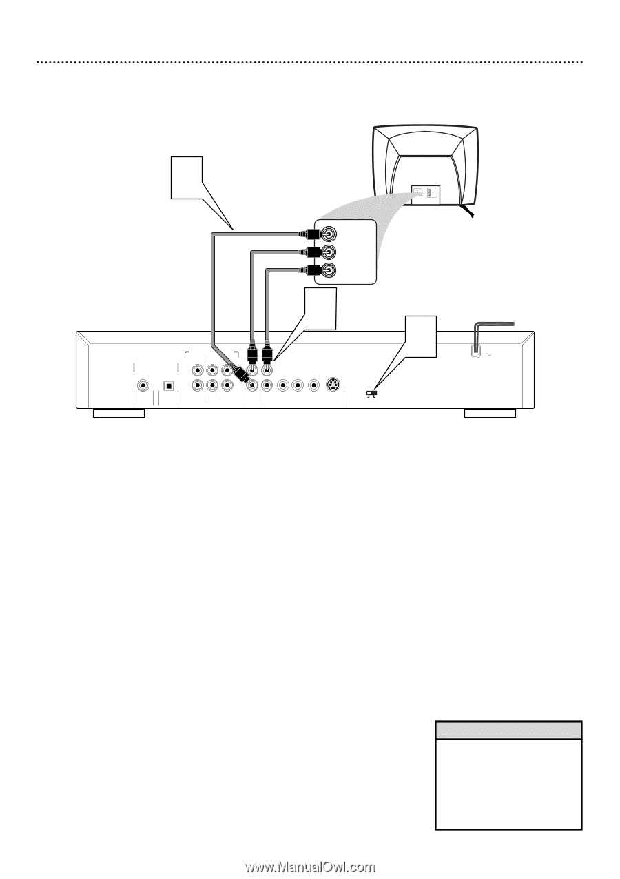
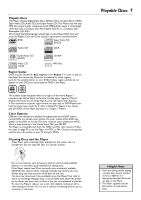
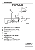
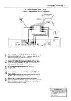
Hookups (cont'd) 9 Connecting to a TV Only TV has a yellow Video In jack 2 Back of TV (example only) RIGHT AUDIO IN LEFT AUDIO IN AUDIO IN RIGHT AUDIO IN LEFT AUDIO IN VIDEO IN 1 DIGITAL AUDIO OUT PCM-MPEG2- Dolby Digital-DTS COAXIAL OPTICAL MULTICHANNEL AUDIO OUT LEFT SURROUND CENTER LEFT FRONT L L 1 R R 2 RIGHT SUBW RIGHT SURROUND FRONT AUDIO CVBS Pr/Cr Pb/Cb Y OUT VIDEO OUT S-VIDEO PROGRESSIVE INTERLACE 3 1 Connect the supplied yellow video cable to the Player's yellow CVBS (VIDEO OUT) jack and to the corresponding VIDEO IN jack on your TV. There are two CVBS (VIDEO OUT) jacks in case you want to connect the Player to two separate TVs. For simply connecting the Player to a single TV, you may use either of the jacks, but you will not have to use both. 2 Connect the supplied red and white audio cables to the Player's red and white (right and left) AUDIO OUT jacks and to the right/left AUDIO IN jacks on the TV. Match the cable colors to the jack colors. 3 Set the PROGRESSIVE/INTERLACE switch to INTERLACE. 4 Connect the power cords of the Player and the TV to a power outlet. Press STANDBY-ON on the front of the Player to turn on the Player. The red Standby light will disappear. 5 Turn on the power of the TV and set the TV to the correct Audio/Video In channel. Such channels may be called AUX or AUXILIARY IN, AUDIO/VIDEO or A/V IN, EXT1 or EXT2, etc. These channels often are near channel 00. See your TV owner's manual for details. Or, change channels at the TV until you see the Player's blue screen saver on the TV screen. Helpful Hint • On the TV, the Video In jack is usually yellow and might be labeled video, CVBS, composite, or baseband. • Your TV may have an RF-style jack. RF modulator details are on page 8.
-
 1
1 -
2
-
3
-
 4
4 -
 5
5 -
 6
6 -
 7
7 -
 8
8 -
 9
9 -
 10
10 -
 11
11 -
 12
12 -
 13
13 -
 14
14 -
15
-
16
-
17
-
18
-
19
-
20
-
21
-
22
-
23
-
24
-
25
-
26
-
27
-
28
-
29
-
30
-
31
-
32
-
33
-
34
-
35
-
36
-
37
-
38
-
39
-
40
-
41
-
42
-
43
-
44
-
45
-
46
-
47
-
48
-
49
-
50
-
51
-
52
-
53
-
54
-
55
 |
 |