Pioneer 607CMX Technical Manual
Pioneer 607CMX - PDP - 60" Plasma Panel Manual
 |
UPC - 012562824413
View all Pioneer 607CMX manuals
Add to My Manuals
Save this manual to your list of manuals |
Pioneer 607CMX manual content summary:
- Pioneer 607CMX | Technical Manual - Page 1
TECHNICAL MANUAL (Ver. 1.1) FOR PIONEER PLASMA DISPLAY MONITOR WHEN USED WITH VIDEO CARDS (EXPANSION SOLUTIONS CARDS) PLASMA DISPLAY MONITOR: PDP-607CMX VIDEO CARD: PDA-5003 / PDA-5004 TABLE TOP STAND: PDK-TS26 WALL MOUNT UNIT: PDK-WM03 SPEAKER SYSTEM: PDP-S55-LR This manual provides precautions - Pioneer 607CMX | Technical Manual - Page 2
65 4.4.3 External Dimensions 65 4.4.4 Stand assembling 66 4.4.5 Attaching the Stand to the Plasma Display ....... 67 4.5 Wall Mount Unit: PDK-WM03 68 4.5.1 Specifications 68 4.5.2 External Dimensions 69 4.5.3 Hardware assembly and Plasma Display attachment 70 4.6 Speaker System: PDP-S55-LR 72 - Pioneer 607CMX | Technical Manual - Page 3
VIDEO WALL Setting 156 12) BAUD RATE Setting 160 13) Assigning an ID 161 14) Cooling Fan Control Setting 163 15) OSD Display this manual and all labels found on the equipment before attempting to mount, dropped objects that can injure people standing or walking below. Tampering with the - Pioneer 607CMX | Technical Manual - Page 4
sections are premised on the PDP607CMX being equipped with the PDA-5003 or PDA-5004. Items that apply only when the PDA-5003 or PDA-5004 is installed are marked with a star '#'. Precautions With the PDA-5003 or the PDA-5004 installed, the PDP-607CMX supports the following functions: Input/output - Pioneer 607CMX | Technical Manual - Page 5
display has a built-in ES Slot Interface to allow card installation for the connection of external devices, thus enhancing its expansion potential. ¶ Supports thinner, lighter, high-endurance design - While producing a large 60" screen image, the display is only 122 mm (4.8") thick, and weighs in at - Pioneer 607CMX | Technical Manual - Page 6
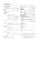
(VESA DDC 2B) supported Audio-related Input AUDIO INPUT (for INPUT1) Stero mini jack L/R 500 mVrms/more than 10 kΩ AUDIO INPUT (for INPUT2) Stero mini jack L/R 500 mVrms/more than 10 kΩ Output AUDIO OUTPUT Stero mini jack L/R 500 mVrms/less than 5 kΩ SPEAKER L/R 6 Ω to 16 Ω/9 W + 9 W (at - Pioneer 607CMX | Technical Manual - Page 7
kH z 70 Hz 87.5 kH z 75 Hz 93.8 kH z 85 Hz 106.3 kH z 59.9 Hz 74.6 kHz CVT 60 Hz 74.0 kHz CVT INPUT 2 7 PC signals supported Resolution (Dot x Line) 640x480 720x400 848x480 852x480 800x600 1024x768 1280x768 1280x800 1280x854 1360x768 1376x768 1152x864 1152x900 1440x900 1280x960 1280x1024 - Pioneer 607CMX | Technical Manual - Page 8
Dimensions 2.2 External Dimensions WEIGHT: 62.0 kg (136.7 lbs) (without stand) MATERIAL: Front: Resin; Rear cover: Metal plate, Front protector panel: Glass TREATMENT: Front: Paint; Rear cover: Paint (All paints are Pioneer original colors) For packaging information, refer to "3.3.2 Unpacking" (pg - Pioneer 607CMX | Technical Manual - Page 9
External Dimensions IR LED 30.3 ø2 ø10 10.5 109 98 367.8 135 150 17 45 99.3 1212 28 38 42 402.8 51 360 98 141.9 9 - Pioneer 607CMX | Technical Manual - Page 10
light indicates an error. 3 Handles Operation panel on the main unit 4 STANDBY/ON button ( ) Press to put the display in Standby or into operation. 5 MENU button Press to open and close the on-screen menu. 6 DISPLAY/SET button Use to confirm on-screen menu selections and to change settings. When - Pioneer 607CMX | Technical Manual - Page 11
of an external left speaker. Connect a speaker that has an impedance of 6 Ω to 16 Ω. 4 RS-232C Never connect any component to this connector without first consulting your Pioneer installation technician. This connector is used for Plasma Display setup adjustments. 5 AUDIO (OUTPUT) (Stereo mini jack - Pioneer 607CMX | Technical Manual - Page 12
OUT (INPUT4) jack when the display is OFF or in Standby. ) AUDIO R/L (INPUT4) (RCA Pin jacks) Use this jack to obtain sound when INPUT4 is selected. Connect these jacks to the component's audio outputs that are connected to the video card's INPUT4. _ COMPONENT VIDEO (INPUT5) (RCA Pin jacks) Use - Pioneer 607CMX | Technical Manual - Page 13
Pin layout 2.4 Pin layout INPUT1 (Mini D-sub, 15-pin connector; female) pin layout 5 1 RS-232C terminal (D-sub 9-pin connector; male) pin layout (DCE format) 1 5 10 6 15 11 Pin No. Input 1R 2G 3B 4 NC (not connected) 5 GND 6 GND 7 GND 8 GND 9 DDC +5V 10 GND 11 NC (not - Pioneer 607CMX | Technical Manual - Page 14
to change subscreen inputs during multiscreen display. 7 SPLIT button Press to switch to multi-screen display. 8 MUTING button Press to mute the volume. 9 ID NO. SET button Press to select which position the panel holds in a video wall. 0 AUTO SET UP button Press to automatically set the [POSITION - Pioneer 607CMX | Technical Manual - Page 15
Plasma Display or its mounting hardware, obtain permission in advance from the building owner walls, check for internal electrical wiring and hidden pipes. 2) Weight capacity of the installation site Select a location sufficient to support the total weight of the display and mounting cause problems. - Pioneer 607CMX | Technical Manual - Page 16
60 °C • Storage humidity: 20 % to 90 % • Operating atmospheric pressure: 800 hPa to 1100 hPa • Storage atmospheric pressure: 700 hPa to 1114 hPa • We discourage installing electronic problem during the winter is condensation forming on or in electronic the Plasma Display in display or contact a Pioneer - Pioneer 607CMX | Technical Manual - Page 17
A draw hot air from the unit. All openings not assisted by fans serve as air inlets. If the unit is hung from or embedded into a wall, special operating temperature limits and other limitations may apply. Refer to section "3.4 Special Installation" (pg. 24) for more information. 17 - Pioneer 607CMX | Technical Manual - Page 18
Screw provided with speaker unit (sold separately) Side view diagram * only for speaker unit Always use a minimum of 4 mounting holes that are the rear panel. Take precautions to prevent the walls from being soiled by the Plasma Display's exhaust outlets. This unit incorporates glass components - Pioneer 607CMX | Technical Manual - Page 19
lines, as shown in the drawing below. Methods of securing Secured at four points (with mounting hardware attached to the top and bottom) *Attach using M8x4. Secured at four points (with mounting hardware attached to the sides) *Attach using M8x4. Take proper precautions to prevent pinching the - Pioneer 607CMX | Technical Manual - Page 20
Mounting surface warping The display incorporates glass. Before mounting the panel using hardware other than that provided by Pioneer, perform the following checks to confirm that the display is negligible. A Mount bolt holes A String String C Plasma Display Mount Surface (Mount Brackets) D - Pioneer 607CMX | Technical Manual - Page 21
or storage, observe the warnings and instructions on the upper face of the carton. • The Plasma Display is made of glass. Please handle the 5 13 Wiping Cloth 14 Operating Instructions 15 Caution Sheet 16 Correction Sheet 6 17 Supplement Sheet 18 Warranty Card 19 Vinyl Bag (S) 20 Dry - Pioneer 607CMX | Technical Manual - Page 22
in the manner shown. No! Never attempt to move the Plasma Display by holding only one of the handles. 3.3.3 Re-packing ( instructions shipped with the unit for information on how to connect a PC or audio device. • Precautions when using long connecting signal cables -- Use coaxial cables. For video - Pioneer 607CMX | Technical Manual - Page 23
, they are not easily removed. * As viewed from the rear of the display. 12 1. Organize cables together using the provided speed clamps. Insert 1 into routed to the right or left. * As viewed from the rear of the display. To remove speed clamps Using pliers, twist the clamp 90° and pull outward - Pioneer 607CMX | Technical Manual - Page 24
Mounting to fittings) 3.4 Special Installation The unit can be hung from or embedded in a wall weight of the display. 7 Take precautions speaker video card other than PDA-5003/PDA-5004 is used, the operating temperature conditions given above may vary. Check the video card operating instructions - Pioneer 607CMX | Technical Manual - Page 25
Special Installation (Mounting to fittings) Standard installation (In cases where top and bottom are reversed) Example 1 Example 2 35 mm or less 35 mm or less Vertical installation Example 3 - Pioneer 607CMX | Technical Manual - Page 26
. However, the figures listed above indicate the distance between the speakers and the wall. Note Different temperature restrictions apply to the PDK-WM03. Refer to "4.5 Wall Mount Unit PDK-WM03" (pg. 68). For a wall-mount installation, allow adequate space (a clearance of 300 mm or more - Pioneer 607CMX | Technical Manual - Page 27
's sides, top and bottom) • Temperature of 0 °C to 35 °C 50 mm or more Ex.: Installation requirements when installed in wall recess Wall-mounted installation (distance between unit and wall greater than 50 mm) Requirements : • Free air flow (With no obstructions within a distance of 300 mm from the - Pioneer 607CMX | Technical Manual - Page 28
wall. Observe all the limitations specified below. Be sure to mount the unit so that twisting, bending, or other deformation of the unit does not exceed 4 mm. (1) Embedding in walls * The same operating temperature restrictions apply to the speaker system (PDP-S55-LR). A - Pioneer 607CMX | Technical Manual - Page 29
Special Installation (Embedding in the wall) Temperature Measurement Points (Illustration for reference purposes) : Thermometer (temperature measurement point) 50 mm 50 mm • Make measurements at a distance of 50 mm from the unit - Pioneer 607CMX | Technical Manual - Page 30
Installation (Embedding in the wall) (2) Embedding in walls with no space provided 40 °C • The same operating temperature restrictions apply to the speaker system (PDP-S55-LR). Methods of Securing: Basic methods of securing to "3.4.1 Mounting to fittings" (pg. 24).) Installation is not possible 30 - Pioneer 607CMX | Technical Manual - Page 31
put in a box) 3.4.4 When the display is put in a box Operating this display in confined spaces is not recommended. • If the display is to be used in a confined causing a malfunction or fire. As a precaution, the inner wall should have sufficient heat resistance or fire resistance. ✩ Usage - Pioneer 607CMX | Technical Manual - Page 32
to separate fittings or parts of the ceiling. Use mounting screws of material stronger than soft steel and use hexagonal bolts. Use wires adequate for the combined weight of the panel and the weight of the support brackets. No! When installing the Plasma Display, DO NOT use the handles as means of - Pioneer 607CMX | Technical Manual - Page 33
the unit to fittings, double-check that the thickness and height of the fittings, and the number of bolts is correct. (Also refer to "3.4.1 Mounting to fittings" (pg. 24).) Horizontal suspension Vertical suspension Attach so that the fan is on the left side when viewed from the rear. Installation - Pioneer 607CMX | Technical Manual - Page 34
Special Installation (Hanging on the wall lengthwise) 3.4.6 Hanging on the wall lengthwise Carefully read the following imformation before attempting to mount the unit on the wall. Observe the various limitations specified below. Be sure to mount the unit so that twisting, bending, or any other - Pioneer 607CMX | Technical Manual - Page 35
air is drawn from the interior of the unit by fans. Before installation, consider the heat resistance of the wall or other surface behind the unit. Exhaust temperatures can be 30 °C higher than the outside temperature. Note For wall-mounting, do not bundle the cables in a way that block vents. 35 - Pioneer 607CMX | Technical Manual - Page 36
upright and flush, embedded in the wall) 3.4.7 Place product upright and flush into wall (embedding in the wall) Carefully read the following instructions before trying to embed the unit in a wall. Observe all the limitations specified below. Be sure to mount the unit so that twisting, bending - Pioneer 607CMX | Technical Manual - Page 37
Installation (Place product upright and flush, embedded in the wall) Methods of Securing: Basic methods of securing are shown of the fittings and the number of fixing bolts is correct. (Also refer to "3.4.1 Mounting to fittings" (pg. 24).) Installation is not possible Attach so that the fan is on - Pioneer 607CMX | Technical Manual - Page 38
Special Installation (Place product upright and flush, embedded in the wall) (2) Embedding in walls with no space provided behind the unit 100 mm or more 100 mm or more 100 mm or more Attach so that the fan is - Pioneer 607CMX | Technical Manual - Page 39
Installation (Place product upright and flush, embedded in the wall) Methods of Securing: Basic methods of securing are shown height of the fittings and the number of bolts is correct. (Also refer to "3.4.1 Mounting to fittings" (pg. 24).) Installation is not possible Attach so that the fan is on the - Pioneer 607CMX | Technical Manual - Page 40
• Ambient temperature: 0 °C to 35 °C • The same operating temperature restrictions apply to the speaker system (PDP-S55-LR). *1 For this installation, set the 'FAN CONTROL' to 'MAX' as shown in fittings and the number of bolts is correct. (Also refer to "3.4.1 Mounting to fittings" (pg. 24).) 40 - Pioneer 607CMX | Technical Manual - Page 41
may rise causing a malfunction or fire. As a precaution, the inner wall should have sufficient heat resistance or fire resistance. • Leave a space at least 10 mm wide when installing glass etc. on the front of the Plasma Display. ✩ Usage temperature conditions (*1) • Ambient temperature: 0 °C to 35 - Pioneer 607CMX | Technical Manual - Page 42
(Horizontal connections) 3.4.9 Horizontal connections While the display is designed to accommodate side-by-side installations, atmosphere in this range. A Unit A Unit B ✩ Operating Temperature Restrictions Distance from wall (A) Ambient temperature 50 mm or more 0 °C to 40 °C 2 Installing three - Pioneer 607CMX | Technical Manual - Page 43
and right partitions are provided. To prevent heat venting from one video wall plasma panel into another panel, each display must be oriented in the same direction. In the above example, each panel is shown with the Pioneer logo at the bottom. ✩ Operating Temperature Restrictions Distance from - Pioneer 607CMX | Technical Manual - Page 44
line or two line audio, thus increasing the uses for video presentations. ¶ Table Top Stand: PDK-TS26 This vertically installed type onboard stand is a perfect match to the 60-inch Plasma Display. ¶ Wall Mount Unit: PDK-WM03 This wall mount unit is made for the 60-inch Plasma Display. It fixes the - Pioneer 607CMX | Technical Manual - Page 45
manual discusses ways to mount, install, and handle the mounting hardware exclusively designed for Pioneer Plasma Displays. Mounting should be performed by qualified experts. Refer all installation and mounting mount screws and other mounting hardware ¶ For worry-free use of the unit: • If problem - Pioneer 607CMX | Technical Manual - Page 46
5004 4.3 Video Card: PDA- video signal (HDCP supported) S-VIDEO jack (Mini-DIN, 4-pin connector) • Y/C separate video video signal Y 1 Vp-p/75 Ω/negative sync. PB/CB, PR/CR 0.7 Vp-p (color 100 %)/75 Ω Audio-related Input AUDIO INPUT (for INPUT3/4) Pin jack (×2) L/R 500 mVrms/more than 10 kΩ AUDIO - Pioneer 607CMX | Technical Manual - Page 47
Video Card: PDA-5003/PDA-5004 7 PDA-5004 Video-related INPUT1 Input INPUT2 Input INPUT3 Input INPUT4 Input INPUT5 Output Input The following signal is supported only when a PDA-5004 is installed. • Component video signal Y 1 Vp-p/75 Ω/negative sync. PB/CB, PR/CR ........ 0.7 Vp-p (color 100 - Pioneer 607CMX | Technical Manual - Page 48
148.9 Video Card: PDA-5003/PDA-5004 4.3.2 External Dimensions (Unit: mm) 7 PDA-5003 262 137.3 7 PDA-5004 301.5 262 27.6 148.3 27.6 137.3 301.5 48 - Pioneer 607CMX | Technical Manual - Page 49
367.8 17 45 Video Card: PDA-5003/PDA-5004 99.3 12 12 28 38 42 32.7 37 402.8 37 18 21.5 14 22 18 18 18 18 36.5 14 130.2 - Pioneer 607CMX | Technical Manual - Page 50
for installation on the Pioneer Plasma Display PDP-607CMX. Installation procedures are as follows: Check the following before installing this video card: • Plasma Display is disconnected from the computer and any other devices. • The Plasma Display is unplugged from the wall outlet before installing - Pioneer 607CMX | Technical Manual - Page 51
ANALOG RGB HD (H/V SYNC) INPUT5 AUDIO 2 Holding the inside tabs, pull the video card straight out. Device mounting surface S-VIDEO INPUT3 VIDEO INPUT4 INPUT 3/4 AUDIO Impedance selector switch 75 Ω ANALOG RGB HD (H/V SYNC) 2.2 kΩ INPUT5 AUDIO Video Card: PDA-5003/PDA-5004 51 - Pioneer 607CMX | Technical Manual - Page 52
's Plug & Play (VESA DDC 2B). 7 When using PDA-5004 Consult the following chart when making connections to a Plasma Display equipped with this video card. Input Connector INPUT INPUT INPUT INPUT INPUT Connected component 1*1 2 3 4 5*1 and signals AV component Analog RGB Component - Pioneer 607CMX | Technical Manual - Page 53
, the PB/CB signal to the PB/CB jack, and the PR/CR signal to the PR/CR jack. Note The Plasma Display and this Video Card are designed to support component video signals with standard, stable signal levels and sync signals. As a result, some image disruption may be generated during use of various - Pioneer 607CMX | Technical Manual - Page 54
Video Card: PDA-5003/PDA-5004 Connection of G ON SYNC analog RGB source Make G ON SYNC connections for a component with output that has the synchronization ON SYNC connections, do not make any connections to the VD or HD jacks. If connections are made, the picture may be not displayed normally. 54 - Pioneer 607CMX | Technical Manual - Page 55
signals and screen sizes that the display is compatible with, please refer to the Plasma Display's Operating Instructions. Connection of separate SYNC analog RGB output impedance of the sync signal is below 75 Ω remove the video card and set the impedance selector switch to 75 Ω. On-screen setup - Pioneer 607CMX | Technical Manual - Page 56
Video Card model being connected, a conversion connector or adapter etc. provided with the computer or sold separately may be necessary. For details, please read your PC's instruction manual an external monitor With the Plasma Display, it is possible to output the video signal to an external monitor - Pioneer 607CMX | Technical Manual - Page 57
below 75 Ω remove the video card and set the impedance selector switch to 75 Ω. On-screen setup is necessary after connection. Notes ÷ When making composite SYNC connections, do not connect anything to the VD jack. If connected to, the picture may not be displayed - Pioneer 607CMX | Technical Manual - Page 58
signals compatible with INPUT2, please refer to the Plasma Display's Operation Instructions. 4.3.8 Connection to INPUT3 Connect an AV component that has S-video output jack to the video card's S-VIDEO (INPUT3) jack. S-VIDEO INPUT3 [When using PDA-5004] VIDEO INPUT4 IN OUT To a monitor or - Pioneer 607CMX | Technical Manual - Page 59
Video Card: PDA-5003/PDA-5004 4.3.10 About DTV set top box connection To ensure proper connection, please carefully read the instruction manual supplied with the DTV set top box. The set top box output signals that this display is compatible with are as follows. Video signal type HDTV Video - Pioneer 607CMX | Technical Manual - Page 60
audio component to the audio input jack of the Plasma Display with installed video card. When the video card is installed, the Plasma Display provides four or five audio input jacks and one audio output jack. Consult the following chart to choose the proper audio input for each video input. Video - Pioneer 607CMX | Technical Manual - Page 61
Video Card: PDA-5003/PDA-5004 [When using PDA-5003] Audio connection for component connected to INPUT3 or INPUT4 INPUT 3/4 AUDIO R L [When using PDA-5004] Audio connection for component connected to INPUT3 INPUT3 AUDIO R L Audio input to the AUDIO R/L (INPUT3/4) pin jacks is possible for - Pioneer 607CMX | Technical Manual - Page 62
Video Card: PDA-5003/PDA-5004 INPUT Response Signals INPUT 1, 5 7 Video signals supported # (applies only when equipped with PDA- 60 33.75 Component 1125i(1080i)/HDTV RGB 1125i(1035i)/HDTV 45.0 Component 750p(720p)/HDTV RGB 67.5 Component 1125p(1080p)/HDTV RGB 7 PC signals supported - Pioneer 607CMX | Technical Manual - Page 63
Video Card: PDA-5003/PDA-5004 INPUT 2 7 Video signals supported # (applies only when equipped with PDA-5003/PDA-5004) Vertical Frequency Fv (Hz) 50 60 Horizontal Frequency Fh (kHz) 28.13 31.25 37.50 31.5 33.75 45.0 Signal Format RGB RGB RGB RGB RGB RGB Remark 1125i(1080i)/HDTV 625p(576p)x720 - Pioneer 607CMX | Technical Manual - Page 64
× 16-15/16 in. (D)) Weight 6.5 kg (14.3 lbs.) (mounting hardware only) 68.5 kg (151.0 lbs.) (mounting hardware and Plasma Display ) Materials Base: Aluminum; Cover: plastic (ABS); Stand stay: Zinc Finish Cover: paint (Pioneer original color) Package dimensions 1080 mm (W) × 257 mm - Pioneer 607CMX | Technical Manual - Page 65
-TS26 4.4.2 Installation coordinates for screws used to attach the stand to a surface * To stabilize the equipment on the floor, use screws least 25 mm (31/32 inch) long. 4.4.3 External Dimensions 7 When using Plasma Display Unit: mm (inch) 1470 (57-7/8) 880 (34-21/32) 501 (19-23/32) [Cente of the - Pioneer 607CMX | Technical Manual - Page 66
boxes Shock absorbing boxes Screws / Securing brackets Operating instructions Attachment Perforated line Bar (Covered with protective sheets) with the pins again. Then tighten it with the included stand assembly screws (M4 × 10 mm). Guide pins 3 Remove the two boxes containing the feet, and set - Pioneer 607CMX | Technical Manual - Page 67
Be sure to take care of the securing wires when moving the stand or Plasma Display. Note that the wires and screws needed to secure the Plasma Display against a wall or pillar or against the stand are not provided with the stand, and that the proper items must be purchased separately in accordance - Pioneer 607CMX | Technical Manual - Page 68
Wall Mount Unit: PDK-WM03 4.5 Wall Mount Unit: PDK-WM03 4.5.1 Specifications External dimensions 950 mm (W) × 613 mm (H) × 45 mm (D) (37-13/32 in. (W) × 24-1/8 in. (H) × 1-25/32 in. (D)) Weight 12.0 kg (26.5 lbs) [mounting hardware only] 74.0 kg (163 lbs) [mounting hardware and plasma display] - Pioneer 607CMX | Technical Manual - Page 69
4.5.2 External Dimensions Unit: mm (inch) Wall Mount Unit: PDK-WM03 15 (19/32) 1470 (57-7/8) 950 (37-13/32) 850 (33-15/32) 530 (20-7/8) 14-10x20 (14-13/32x25/32) Center of the display 2-ø8.5 (2-ø11/32) [Set screw position] Center of the display 2-8.5x12 (2-11/32x15/32) [Set screw position] - Pioneer 607CMX | Technical Manual - Page 70
Wall Mount Unit: PDK-WM03 4.5.3 Hardware assembly and Plasma Display attachment 1) Attaching the metal fittings The display comes with left side hardware and right side hardware. Do the installation so that the two eyebolts are both on the inside. Eyebolt É" 9 Left Right 1 - Pioneer 607CMX | Technical Manual - Page 71
Wall Mount Unit: PDK-WM03 3) Installing the Plasma Display With the display metal fitting already attached to the Plasma Display, attach the plasma display to the hung on wall unit. 1 Hang the top hooks of the left and right display metal fittings on the groove in the hung on wall unit. Top hook 2 - Pioneer 607CMX | Technical Manual - Page 72
151.7 lbs.) (when mounted to the Plasma Display ) Dimensions of packaging ......... 950 mm (W) × 295 mm (H) × 390 mm (D) (37-13/32 in. (W) × 11-5/8 in. (H) × 15-11/32 in. (D)) Package weight 10.3 kg (22.7 lbs.) Layers of packing 10 layers Model 2-way, 3-speaker system (bass-reflection - Pioneer 607CMX | Technical Manual - Page 73
Speaker System: PDP-S55-LR 4.6.2 External Dimensions (when mounted to the Plasma Display) Unit: mm (inch) *1: Dimension from the front surface of the speaker to the attachment pieces. *2: Size of Plasma Display 39 (1-17/32) 99 (3-29/32) 96 (3-25/32) 119 (4-11/16) *1 90 (3-17/32) 1651 (65) 90 - Pioneer 607CMX | Technical Manual - Page 74
of the speakers. 3 Loosely screwing the screws (M5) into place on the top attachment pieces (two locations). Note: To install the Plasma Display on a wall, first attach the attachment pieces to the Plasma Display then install it on the wall. After installing the Plasma Display on the wall, it may - Pioneer 607CMX | Technical Manual - Page 75
After adjustment, re-tighten the screws. ¶ To install the Plasma Display on a wall, it is recommended that you first remove the speaker units, then after the Plasma Display has been installed on the wall, re-attach the speaker units to the Plasma Display. 2) Connect the cords (Turn off the power of - Pioneer 607CMX | Technical Manual - Page 76
Speaker System: PDP-S55-LR 3) Care and Maintenance When the cabinet gets dirty... • Wipe with nozzle adapter. • To prevent damage to the cabinet and speaker nets, do not scrach or hit them with hard objects. Also, do not stab the speaker nets with sharp objects. Do not apply volatile chemicals such - Pioneer 607CMX | Technical Manual - Page 77
Speaker System: PDP-S55-LR 77 - Pioneer 607CMX | Technical Manual - Page 78
management standby state No input ON indicator flashes INPUT1 to INPUT5 MENU 1 Normal operation mode MENU (Note 1) DISPLAY Press for three seconds or more. DISPLAY MENU 2 Menu Mode 3 Integrator Mode 4 RS-232C Adjustment indicates the operation modes and states indicates button controls - Pioneer 607CMX | Technical Manual - Page 79
Before Beginning Adjustments 3 Integrator Mode This mode provides an adjustment function for integrator options. This mode has white-balance adjustment and various detailed settings in addition to the items in the menu mode. For details, refer to section 5.4, "Integrator Mode" (pg. 142). 4 RS-232C - Pioneer 607CMX | Technical Manual - Page 80
75 Hz 85.1 Hz 99.8 Hz 120 Hz 74.6 Hz 37.9 kHz 48.1 kHz 46.9 kHz 53.7 kHz 63.0 kHz 75.7 kHz 49.7 kHz 60 Hz 48.4 kHz 60 Hz 70.1 Hz 49.7 kHz 56.5 kHz Screen size (Dot x line) DOT BY DOT 4:3 FULL 640x400 720x400 ± 640x480 848x480 852x480 800x600 832x624 1024x768 - Pioneer 607CMX | Technical Manual - Page 81
Hz 75.0 kHz 65 Hz 70 Hz 75 Hz 85 Hz 59.9 Hz 81.3 kHz 87.5 kHz 93.8 kHz 106.3 kHz 74.6 kHz 60 Hz 74.0 kHz Screen size (Dot x line) DOT BY DOT 4:3 FULL 1024x768 ± 1024x768 1024x768 ± ± 1024x768 ± ± ± ± 1365x768 1365x768 ± 1365x768 1365x768 ± ± 1365x768 1365x768 ± ± ± ± 1365x768 1365x768 - Pioneer 607CMX | Technical Manual - Page 82
kHz 64.6 kHz 75.1 kHz 78.1 kHz 80.0 kHz 81.1 kHz 91.1 kHz 65.3 kHz 82.3 kHz 65.3 kHz 50 Hz 56.2 kHz 60 Hz 60 Hz 67.5 kHz 75.0 kHz 60 Hz 74.0 kHz Screen size (Dot x line) DOT BY DOT 4:3 FULL 1024x768 1280x768 ± ± 1360x768 1024x768 ± ± 1024x768 ± 1024x768 ± 1024x768 1024x768 ± 1024x768 - Pioneer 607CMX | Technical Manual - Page 83
should not be used unless required). FULL This is for wide-screen video (squeeze) (For a 16:9 source, roundness is nearly accurate). Personal computer signal when the input signals a less than the pixels of the plasma display. For details, refer to the correspondence signal table. 100 100 100 - Pioneer 607CMX | Technical Manual - Page 84
Input correspondence signals (video signals) # (Applicable supported but can be displayed (not recorded in EDID data). Vertical Horizontal fV (Hz) fH (kHz) Signal format Screen size 4:3 FULL ZOOM WIDE 14:9 2.35:1 Remarks 15.6 RGB 625i(576i)/SDTV 50 56.25 RGB 1125p(1080p)/HDTV 15.8 60 - Pioneer 607CMX | Technical Manual - Page 85
Video (Y/C) ‡ ‡ ‡ ‡ ‡ ‡ ‡ S-Video (Y/C) ‡ ‡ ‡ ‡ ‡ ‡ ‡ S-Video (Y/C) ‡ ‡ ‡ ‡ ‡ ‡ ‡ S-Video (Y/C) ‡ ‡ ‡ ‡ ‡ ‡ ‡ S-Video (Y/C) ‡ ‡ ‡ ‡ ‡ ‡ ‡ S-Video ‡ ‡ ‡ ‡ ‡ Remark • 'UNDERSCAN' is for display-screen sizes other than those given in the table above. This - Pioneer 607CMX | Technical Manual - Page 86
75 Hz 85.1 Hz 99.8 Hz 120 Hz 74.6 Hz 37.9 kHz 48.1 kHz 46.9 kHz 53.7 kHz 63.0 kHz 75.7 kHz 49.7 kHz 60 Hz 48.4 kHz 60 Hz 70.1 Hz 49.7 kHz 56.5 kHz Screen size (Dot x line) DOT BY DOT 4:3 FULL 640x400 720x400 ± 640x480 848x480 852x480 800x600 832x624 1024x768 - Pioneer 607CMX | Technical Manual - Page 87
Hz 75.0 kHz 65 Hz 70 Hz 75 Hz 85 Hz 59.9 Hz 81.3 kHz 87.5 kHz 93.8 kHz 106.3 kHz 74.6 kHz 60 Hz 74.0 kHz Screen size (Dot x line) DOT BY DOT 4:3 FULL 1024x768 ± 1024x768 1024x768 ± ± 1024x768 ± ± ± ± 1365x768 1365x768 ± 1365x768 1365x768 ± ± 1365x768 1365x768 ± ± ± ± 1365x768 1365x768 - Pioneer 607CMX | Technical Manual - Page 88
kHz 64.6 kHz 75.1 kHz 78.1 kHz 80.0 kHz 81.1 kHz 91.1 kHz 65.3 kHz 82.3 kHz 65.3 kHz 50 Hz 56.2 kHz 60 Hz 60 Hz 67.5 kHz 75.0 kHz 60 Hz 74.0 kHz Screen size (Dot x line) DOT BY DOT 4:3 FULL 1024x768 1280x768 ± ± 1360x768 1024x768 ± ± 1024x768 ± 1024x768 ± 1024x768 1024x768 ± 1024x768 - Pioneer 607CMX | Technical Manual - Page 89
size Screen size DOT BY DOT The input signal corresponds 1:1 with the pixels of the Plasma Display for an accurate reproduction. When a video card is installed Video signal 4:3 source Video signal 16:9 source (NTSC, 625i, etc.) (750p, 1080i, etc.) 4:3 For a 4:3 source, roundness can be - Pioneer 607CMX | Technical Manual - Page 90
Before Beginning Adjustments 5.1.4 List of Adjustable and Settable Items 1) Menu Mode 7 PDP-607CMX *1: INPUT1 case *2: INPUT2 case (Note 1) The OPTION settings are common settings for all inputs. 90 - Pioneer 607CMX | Technical Manual - Page 91
7 PDP-607CMX# Before Beginning Adjustments #: Applicable only when a PDA-5003/PDA-5004 is installed. : Cannot be set according to the signal. *1: INPUT1 case *2: INPUT2 case (Note 1) The OPTION settings are common settings for all inputs. 91 - Pioneer 607CMX | Technical Manual - Page 92
Before Beginning Adjustments 7 PDA-5003/PDA-5004 #: Applicable only when a PDA-5003/PDA-5004 is installed. : Cannot be set according to the signal. *1: INPUT5 case *2: INPUT3 or INPUT4 cases (Note 1) The OPTION settings are common settings for all inputs. 92 - Pioneer 607CMX | Technical Manual - Page 93
other than PDA-5003/PDA-5004 Before Beginning Adjustments #: Applicable only when a video card is installed. : Cannot be set according to the signal. *1: INPUT3 to INPUT5 analog signal cases *2: INPUT3 to INPUT5 digital signal cases (Note 1) The OPTION settings - Pioneer 607CMX | Technical Manual - Page 94
Before Beginning Adjustments 2) Integrator mode 7 PDP-607CMX (Note) The OPTION settings are common settings for all inputs. 94 - Pioneer 607CMX | Technical Manual - Page 95
7 PDP-607CMX# Before Beginning Adjustments : Applicable only when a PDA-5003/PDA-5004 is installed. (Note) The OPTION settings are common settings for all inputs. 95 - Pioneer 607CMX | Technical Manual - Page 96
Before Beginning Adjustments 7 PDA-5003/PDA-5004 : INPUT3 to INPUT5 are applicable only when the PDA-5003 or the PDA-5004 is installed. (Note) The OPTION settings are common settings for all inputs. 96 - Pioneer 607CMX | Technical Manual - Page 97
7 Slot card other than PDA-5003/PDA-5004 Before Beginning Adjustments : INPUT3 to INPUT5 are applicable only when the PDA-5003 or the PDA-5004 is installed. (Note) The OPTION settings are common settings for all inputs. 97 - Pioneer 607CMX | Technical Manual - Page 98
• Three seconds after an operation • When the standby mode is designated by a remote-control, main-control panel or command • When the format of the displayed signal changes (NOTE) Of the RS-232C commands that can be used in the normal-operation mode, there are some that cannot be saved in - Pioneer 607CMX | Technical Manual - Page 99
are possible. B Pressing the [DISPLAY] button on the remote control or main-control panel again for three seconds or more when the display described in A above is displayed, cause various settings and internal temperature to be displayed as shown below (DISPLAY CALL 2). PDP-607CMX SERIAL NO. LOT - Pioneer 607CMX | Technical Manual - Page 100
When the [PIP SHIFT] button on the remote control is pressed during a PinP screen display, the display position of the sub screen changes as shown below. 3 • While the video wall is set, multi-screen display is unavailable. • When the video wall is set or during multi-screen display, point zoom is - Pioneer 607CMX | Technical Manual - Page 101
mode causes the menu screen to appear. Pressing the [MENU] button while in the menu adjustments, refer to the Operating Instructions. (3) It is recommended that possible when no video signal is input. 5.3.2 Concerning the display of the OSD of each item Example of Menu Display: MENU PICTURE - Pioneer 607CMX | Technical Manual - Page 102
Operation The basic operation in the menu mode will be explained using brightness adjustment as an example. 1 Press the MENU button to display the menu screen. MENU PICTURE SCREEN CONTRAST BRIGHTNESS H.ENHANCE V. E N H A N C E PICTURE RESET SETUP : : : : INPUT1 OPTION 0 0 0 0 SET ENTER MENU - Pioneer 607CMX | Technical Manual - Page 103
and setting in the Menu Mode 1) Power Management Setting When no video signal (synchronizing signal) is detected, this function automatically sets the energy computer. After operating the personal computer, press the [INPUT] button. • The power consumption during power standby. PDP-607CMX: 0.8 W 103 - Pioneer 607CMX | Technical Manual - Page 104
display automatically identifies PC signals and video MENU EXIT 3 Press the [2/3] buttons to change the setting. Each time a [2/3] button is pressed, the signal format Hz] 70.0 60.0 60.0 60.0 56.0 60.0 60.0 70.0 75.0 56.0 59.8 60.0 70.0 H [kHz] 31.5 31.5 31.0 31.7 35.2 48.4 49.7 56.5 60.0 45.1 - Pioneer 607CMX | Technical Manual - Page 105
Neg. - Pos. Neg. Pos. Neg. - V [Hz] 60.0 59.9 60.0 60.0 60.0 75.0 60.0 59.9 60.0 50.0 H [kHz] 47.7 48.3 49.7 53.1 53.7 67 2 3 DEUTSCH 2 With the desired language displayed, press the [SET] button. Screen 3 LANGUAGE SET SET Note Setting the display language for either INPUT1 or INPUT2 sets the - Pioneer 607CMX | Technical Manual - Page 106
SAVE: MUTE' and press the MENU button. Image mute starts at the same time that the menu disappears. Factory setting: STANDARD Differences in video reproduction by energy saving settings (illustration) For this kind of input signal (As a standard) When the white window is displayed, the peak - Pioneer 607CMX | Technical Manual - Page 107
1 Select 'OPTION'. Menu Mode 2 Place the cursor over 'ENERGY SAVE' then press the [SET] button to change the setting. Each time the [SET] button is pressed, the setting changes as shown below. 3 STANDARD 3 MODE1 3 MODE2 MUTE 2 MODE3 2 The 'ENERGY SAVE' setting is common for all inputs. - Pioneer 607CMX | Technical Manual - Page 108
the [SET] button. 3 Place the cursor on 'PRESENT TIME' then press the [SET] button. 4 Adjust each item by pressing the 5/∞/2/3 buttons. DAYLIGHT SAVING TIME ..... sets daylight savings time ON: Displays time as present time + one hour OFF: Disables [DAYLIGHT SAVING TIME] mode Week Set current day - Pioneer 607CMX | Technical Manual - Page 109
). Setting 'MODE1' to 'MODE3' is effective in reducing screen burn when a still image is displayed. Factory setting: OFF 1 Select 'OPTION'. 2 Place the cursor on 'SCREEN MGT.' then press the [SET] button. Screen 2 MENU PICTURE SCREEN LANGUAGE ENERGY SAVE TIMER SETTING S C R E E N M G T. AUTO SETUP - Pioneer 607CMX | Technical Manual - Page 110
Setting Images are softened by suppressing the edge contrast. Factory setting: OFF 1 Select 'OPTION'. 2 Place the cursor on 'SCREEN MGT.' then press the [SET] button. Screen 2 MENU PICTURE SCREEN LANGUAGE ENERGY SAVE TIMER SETTING S C R E E N M G T. AUTO SETUP MODE AUTO FUNCTION PIP DETECT SPLIT - Pioneer 607CMX | Technical Manual - Page 111
items are the same as when the 'AUTO SET UP' button is pressed on the remote control; however, precision may be a little inferior. This ACTIVE and 'SCREEN' is manually adjusted, 'AUTO SETUP MODE: ACTIVE' is displayed. This is to warn you that although adjustment is manual, when the input changes or - Pioneer 607CMX | Technical Manual - Page 112
refer to the procedure below and make the adjustment manually. Example) When a PC signal is input to 'SCREEN'. 3 Place the cursor on 'POSITION' then press the [SET] button. Screen 2 MENU PICTURE POSITION of the video display are properly set. 1. With the [∞] button, lower the display until the - Pioneer 607CMX | Technical Manual - Page 113
of the screen moves. With 'POSITION', accurately adjust the left side of the video display again. As in step 4, used the [2/3] buttons to align the left side. signal having edges is input. 9 Place the cursor on 'PHASE' then press the [SET] button. 0 Using the [2/3] buttons adjust the clock phase. - Pioneer 607CMX | Technical Manual - Page 114
. • After the input has been switched in the Auto Function mode, press the [INPUT] button and select a different input. The Auto Function mode The Auto Function mode is unavailable when the Menu displays, during POINT ZOOM, or during multi-screen display. • When the Auto Function mode is set to - Pioneer 607CMX | Technical Manual - Page 115
. The subscreen mode function is disabled during side-by-side display. * The lack of a subscreen input signal means there is no video signal or sync signal. Factory setting: ACTIVE 1 Select 'OPTION'. 2 Place the cursor on 'PIP DETECT' then press the [SET] button to change the setting. Each time the - Pioneer 607CMX | Technical Manual - Page 116
as shown below. 3 OFF 3 S BY S 3 PIP • OFF The still picture displayed at the time the FREEZE button was pressed is displayed as a single fullscreen image • S BY S ....... When the FREEZE button is pressed, the freeze-frame image is displayed in the sideby-side subscreen • PIP When the FREEZE - Pioneer 607CMX | Technical Manual - Page 117
a PDA-5003/PDA5004 is installed.) The basic operation in the menu mode is explained using brightness adjustment as an example. 1 Press the MENU button to display the menu screen. MENU PICTURE SCREEN CONTRAST BRIGHTNESS COLOR TINT SHARPNESS PICTURE RESET SET ENTER SETUP : : : : : INPUT1 OPTION - Pioneer 607CMX | Technical Manual - Page 118
HIGH: Corresponds to + 1000 k • HIGH: Corresponds to + 2000 k Settable condition: When there is video signal input Factory setting: MIDDLE 1 Select 'SETUP'. 2 Place the cursor over 'COLOR TEMP.' then press the [SET] button. Screen 2 MENU PICTURE SCREEN C O L O R T E M P. AUTO POWER OFF DNR MPEG - Pioneer 607CMX | Technical Manual - Page 119
video pressing the [INPUT] button on the remote control or the main operating panel. But during G ON SYNC input, only operating the personal computer will not cause it to return. After operating the personal computer, press the [INPUT] button. • The power consumption during power standby. PDP-607CMX - Pioneer 607CMX | Technical Manual - Page 120
reduction) setting can be changed to improve the S/N ratio when a video signal is input. The setting should be performed for each input ( pressed, the setting changes as shown below. 3 HIGH 2 3 OFF 2 3 MIDDLE 2 3 LOW 2 Screen 3 Note DNR is unavailable during 1080p signal or multi screen display - Pioneer 607CMX | Technical Manual - Page 121
be performed for each input (INPUT1 to INPUT5) and each signal. Settable condition: When there is video signal input Factory setting: LOW 1 Select 'SETUP'. 2 Place the cursor over 'MPEG NR' then press the [SET] button. Screen 2 MENU PICTURE SCREEN C O L O R T E M P. AUTO POWER OFF DNR MPEG NR CTI - Pioneer 607CMX | Technical Manual - Page 122
be performed for each input (INPUT1 to INPUT5) and each signal. Settable condition: When there is video signal input Factory setting: ON 1 Select 'SETUP'. 2 Place the cursor over 'CTI' then press the [SET] button. Screen 2 MENU PICTURE SCREEN C O L O R T E M P. AUTO POWER OFF DNR MPEG NR CTI - Pioneer 607CMX | Technical Manual - Page 123
performed for each input (INPUT1 to INPUT5) and each signal. Settable condition: When there is video signal input Factory setting: ON 1 Select 'SETUP'. 2 Place the cursor over 'PURECINEMA' then press the [SET] button. Screen 2 MENU PICTURE SCREEN C O L O R T E M P. AUTO POWER OFF DNR MPEG NR CTI - Pioneer 607CMX | Technical Manual - Page 124
. Types of display call signals 625i (576i)/SDTV 1125i (1080i)/HDTV 625p (576p)/SDTV 750p (720p)/HDTV 1125p (1080p)/HDTV 1250p/HDTV 525i (480i)/SDTV 525p (480p)/SDTV 1125i (1080i)/HDTV 1125i (1035i)/HDTV 750p (720p)/HDTV 1125p (1080p)/HDTV INPUT2 Refresh rate Vertical fV (Hz) 50 60 Horizontal fH - Pioneer 607CMX | Technical Manual - Page 125
time the [SET] button is pressed, the setting changes as shown below. 3 RGB 3 COMPONENT1 COMPONENT22 Set 'COLOR DECODING' as follows. Please take care when assigning settings. Incorrect settings can adversely affect the Plasma Display. Connected component SETUP Component video output of Y/Cb/Cr - Pioneer 607CMX | Technical Manual - Page 126
INPUT3 and INPUT4 correspond to and automatically determine the various TV systems used in countries around the world. Normally, this Place the cursor over 'COLOR SYSTEM' then press the [SET] button to change the setting. Each time the [SET] button is pressed, the setting changes as shown below. 3 - Pioneer 607CMX | Technical Manual - Page 127
installed] Menu Mode 9) Signal Format Setting This display automatically identifies PC signals and video signals such as from a DVD player by the OFF :RGB :AUTO MENU EXIT 3 Press the [2/3] buttons to change the setting. Each time a [2/3] button is pressed, the signal format changes as shown - Pioneer 607CMX | Technical Manual - Page 128
/PDA-5004 is installed] If it is not displayed correctly when "AUTO" has been set, change Video signal Resolution 525p 576p 750p 1125i (1080i) 1125i (1035i) 1125i (1080i) 1080p 1125p 1250p V H polarity polarity - - - - - - - - - - - - - - - - - - V [Hz] 60 50 60 50 60 60 50 60 - Pioneer 607CMX | Technical Manual - Page 129
SETUP :OFF INPUT1 OPTION 3 Place the cursor over 'PLUG/PLAY' and press the [2/3] button to change the setting. Each time a [2/3] button is pressed, the setting changes as shown below. 3 PC 2 3 VIDEO* 2 * Applicable only when the video card is installed. SET ENTER Screen 3 MENU EXIT DVI SET UP - Pioneer 607CMX | Technical Manual - Page 130
LANGUAGE SET SET : ENGLISH MENU EXIT 3 Each time a [2/3] button is pressed, the language changes as shown below. 3 ENGLISH 2 3 2 3 FRANÇAIS 2 3 ITALIANO 2 3 ESPAÑOL 2 3 DEUTSCH 2 With the desired language displayed, press the [SET] button. Screen 3 Note LANGUAGE SET SET : FRANÇAIS MENU - Pioneer 607CMX | Technical Manual - Page 131
SAVE: MUTE' and press the MENU button. Image mute starts at the same time that the menu disappears. Factory setting: STANDARD Differences in video reproduction by energy saving settings (illustration) For this kind of input signal (As a standard) When the white window is displayed, the peak - Pioneer 607CMX | Technical Manual - Page 132
[Applicable only when a PDA-5003/PDA-5004 is installed] 2 Place the cursor over 'ENERGY SAVE' then press the [SET] button to change the setting. Each time the [SET] button is pressed, the setting changes as shown below. 3 STANDARD 3 MODE1 3 MODE2 MUTE 2 MODE3 2 The 'ENERGY SAVE' setting is - Pioneer 607CMX | Technical Manual - Page 133
the [SET] button. 3 Place the cursor on 'PRESENT TIME' then press the [SET] button. 4 Adjust each item by pressing the 5/∞/2/3 buttons. DAYLIGHT SAVING TIME ..... sets daylight savings time ON: Displays time as present time + one hour OFF: Disables [DAYLIGHT SAVING TIME] mode Week Set current day - Pioneer 607CMX | Technical Manual - Page 134
). Setting 'MODE1' to 'MODE3' is effective in reducing screen burn when a still image is displayed. Factory setting: OFF 1 Select 'OPTION'. 2 Place the cursor on 'SCREEN MGT.' then press the [SET] button. Screen 2 MENU PICTURE SCREEN LANGUAGE ENERGY SAVE TIMER SETTING S C R E E N M G T. AUTO SETUP - Pioneer 607CMX | Technical Manual - Page 135
are softened by suppressing the edge contrast. Factory setting: OFF Menu Mode 1 Select 'OPTION'. 2 Place the cursor on 'SCREEN MGT.' then press the [SET] button. Screen 2 MENU PICTURE SCREEN LANGUAGE ENERGY SAVE TIMER SETTING S C R E E N M G T. AUTO SETUP MODE AUTO FUNCTION PIP DETECT SPLIT - Pioneer 607CMX | Technical Manual - Page 136
items are the same as when the 'AUTO SET UP' button is pressed on the remote control. However, the screen may be less precise. This and the 'SCREEN' is adjusted manually, 'AUTO SETUP MODE: ACTIVE' is displayed. This is to warn you that although adjustment is manual, when the input changes, or - Pioneer 607CMX | Technical Manual - Page 137
signal, adjustment may be off. In this situation, manually adjust the setting. Example) When a PC signal SCREEN'. 3 Place the cursor on 'POSITION' then press the [SET] button. Screen 2 MENU PICTURE POSITION of the video display are properly set. 1. With the [∞] button, lower the display until the - Pioneer 607CMX | Technical Manual - Page 138
side of the screen moves. With 'POSITION', accurately adjust the left side of the video display again. As in step 4, used the [2/3] buttons to align the left side. the input signal has edges. 9 Place the cursor on 'PHASE' then press the [SET] button. 0 Using the [2/3] buttons to adjust the clock - Pioneer 607CMX | Technical Manual - Page 139
switched in the Auto Function mode, press the [INPUT] button and select a displays, during POINT ZOOM, or during multi-screen display. • When the Auto Function mode is set to 'INPUT1' or 'INPUT4', 'AUTO' appears under the option that displays the selected input (INPUT1 to INPUT5). • When a video card - Pioneer 607CMX | Technical Manual - Page 140
. The subscreen mode function is disabled during side-by-side display. * The lack of a subscreen input signal means there is no video signal or sync signal. Factory setting: ACTIVE 1 Select 'OPTION'. 2 Place the cursor on 'PIP DETECT' then press the [SET] button to change the setting. Each time the - Pioneer 607CMX | Technical Manual - Page 141
when a PDA-5003/PDA-5004 is installed] Menu Mode 21) SPLIT FREEZE Setting For setting other than [OFF], the image displayed when the FREEZE button is pressed is displayed in a subscreen as a freeze-frame image. Factory setting: OFF 1 Select 'OPTION'. 2 Place the cursor on 'SPLIT FREEZE' then - Pioneer 607CMX | Technical Manual - Page 142
) is not supported. (4) Only English is supported in the integrator mode. (5) During Point Zoom operation or multi-screen display, 'DISPLAY CALL 1' is unavailable even if the [DISPLAY] button is pressed. After disengaging Point Zoom or multi-screen display, follow the instructions under 1) Entering - Pioneer 607CMX | Technical Manual - Page 143
desired picture. FH : 31.5kHz FV : 60.0Hz 640X480 POL.H : NEGA POL.V : POSI FULL 3 Press the [DISPLAY] button on the remote control unit or the main-control panel (three seconds or more) when 'DISPLAY CALL 1' is displayed to display 'DISPLAY CALL 2'. PDP-607CMX SERIAL NO. LOT D AT E HOUR METER - Pioneer 607CMX | Technical Manual - Page 144
PICTURE adjustment (refer to the instruction manual). • PC input CONTRAST, BRIGHTNESS, H. ENHANCE, V. ENHANCE, etc. • Video input # (Applicable only when value adjusted here becomes the center value for adjustment in the menu mode. Press the [SET] button to return to screen 1-1 or screen 2-2. For - Pioneer 607CMX | Technical Manual - Page 145
mode. (Refer to section 5.4.1, "About the Integrator Mode" (pg. 142).) Select 'PICTURE'. 2 Place the cursor on 'WHITE BALANCE' then press the [SET] button. Screen 1 I N T E G R ATO R INPUT1 PICTURE SCREEN CONT RA ST B R I GHTNESS H . ENHANCE V . ENHANCE WH I T E BALANCE C OLOR DETA I L G AMMA - Pioneer 607CMX | Technical Manual - Page 146
mode. (Refer to section 5.4.1, "About the Integrator Mode" (pg. 142).) 2 Select 'PICTURE'. 3 Place the cursor on 'COLOR DETAIL' then press the [SET] button. Screen 3 I N T E G R ATO R INPUT1 PICTURE SCREEN CONT RA ST B R I GHTNESS H . ENHANCE V . ENHANCE WH I T E BALANCE C OLOR DETA I L G AMMA - Pioneer 607CMX | Technical Manual - Page 147
the setting changes as shown below. 31.8 2 3 1.9 2 3 2.0 2 3 2.1 2 3 2.4 2 3 2.3 2 3 2.2 2 Press the [SET] button to return to screen 3. Screen 4 GAMMA SET SET : 2.0 MENU EXIT Note • The GAMMA value is set based on Pioneer's measurement standards. • After adjusting the WHITE BALANCE, the WHITE - Pioneer 607CMX | Technical Manual - Page 148
MENU EXIT The values adjusted here become the menu mode's initial values. Press the [SET] button to return to screen 2. input: 0 to 255 (initial value: 128) H. POSITION, V. POSITION when there is video signal input: 0 to 127 (initial value: 64) (When a PDA-5003/PDA5004 is used - Pioneer 607CMX | Technical Manual - Page 149
ENHANCE setting for each input (INPUT1 to INPUT5). Also, perform the setting for both PC and video signals. After setting is complete, press the [SET] button to return to screen 3. Note During video wall, the BRT. ENHANCE function is unavailable, however, settings can still be changed. Screen 4 BRT - Pioneer 607CMX | Technical Manual - Page 150
, for example a DVD player and a PC. After muting the audio before hand, enter the integrator mode and perform the adjustment. 1 Enter the [2/3] buttons on the remote control or the maincontrol panel to change settings. Press the [SET] button to return to screen 3. Screen 4 - Pioneer 607CMX | Technical Manual - Page 151
SEL. SET ADJ MENU EXIT 5 Change the setting with the [5/∞/2/3] buttons then press the [SET] button. Screen 5 7 Program timer settings DATE Sets the day of executed when the power is turned ON ORB Sets the Orbiter INV Displays inverted REP.1 .......... Sets the REPEAT 1 input mode. REP.2 - Pioneer 607CMX | Technical Manual - Page 152
" (state when the power is off) setting. Example: At 8:00 AM on Monday, turn on the power and display the input from INPUT1, then at 9:00 AM, display the input from INPUT2, at 10;00AM, display white, and turn off the power at 11:00 AM. Program 1 Program 2 Program 3 8:00 INPUT1 9:00 10 - Pioneer 607CMX | Technical Manual - Page 153
Plasma Display. When setting something other than 'OFF' or 'INVERSE' it is not possible to display a signal input. When the screen has been burned, this function may be used as an emergency measure for relieving the problem cursor on 'SCREEN MASK' then press the [SET] button to change the - Pioneer 607CMX | Technical Manual - Page 154
(pg. 142).) 2 Select 'OPTION'. 3 Place the cursor on 'SIDE MASK' then press the [SET] button. Screen 3 I N T E G R ATO R INPUT1 PICTURE display. • It is only effective during INPUT2 and INPUT5 color signal. • Compatible signals: 1080i, 720p, 1080p • It takes about five seconds until display - Pioneer 607CMX | Technical Manual - Page 155
6 Place the cursor on 'DEFAULT' then press the [SET] button to return to the factory setting. The 'SIDE MASK' settings are common for all inputs. Screen 6 Integrator Mode SIDE MASK R. LEVEL G. LEVEL B . LEVEL AUTO SIDE MASK D E FAU LT RETURN : 80 : 80 : 80 : OFF SET MENU EXIT 155 - Pioneer 607CMX | Technical Manual - Page 156
-panel video wall. Note This setting is adjusted when the screen size is full display. It is not correctly displayed in About the Integrator Mode" (pg. 142).) 2 Select 'OPTION'. 3 Place the cursor on 'VIDEO WALL' then press the [SET] button. Screen 3 I N T E G R ATO R INPUT1 PICTURE SCREEN - Pioneer 607CMX | Technical Manual - Page 157
the video wall. 6 Place the cursor on 'POSITION' then press the [SET] button. Note Set 'DIVIDER' at other than 'OFF' and '1'. Screen 6 VIDEO WALL part where the displays are combined. Screen 7 V I D EO WA L L POS I T I O N POS I T ION NO. : 16 SET SET MENU EXIT Screen 8 VIDEO WALL D I V - Pioneer 607CMX | Technical Manual - Page 158
ID When 'ON' is set, the ID for each of the multiple displays linked by the remote control cable is set automatically. 9 Place the cursor on 'AUTO ID' then press the [SET] button. Screen 9 VIDEO WALL D I V I DER POS I T I ON T YPE AUTO I D P . O N D E L AY ABL L I NK RETURN : 25 : NORMAL : OFF - Pioneer 607CMX | Technical Manual - Page 159
is pressed, the setting changes as shown below. 3 ON 2 3 OFF 2 [Setting the ABL LINK] ON Brightness of each screen on the video wall is the same (available for four panel and nine panel video walls only). OFF ......... Brightness of the screens depends on the setting of each display. [Connecting - Pioneer 607CMX | Technical Manual - Page 160
cursor on 'BAUD RATE' then press the [SET] button to change the setting. Each time the [SET] button is pressed, the setting changes as shown below The 'BAUD RATE' setting is common for all inputs. Set the baud rate of the display so that it matches the baud rate of the PC. Also, if the RS-232C cable - Pioneer 607CMX | Technical Manual - Page 161
This option assigns the ID necessary to adjust only the designated display in a video wall or to make an adjustment using an RS-232C command. For Press the [SET] button to return to screen 3. The 'ID NO. SET' settings are common for all inputs. 7 The Remote Control ID When several Plasma Displays - Pioneer 607CMX | Technical Manual - Page 162
press [CLEAR] button, the setting back 'ALL'. • This function does not assign an ID number to the remote control; it assigns two kinds of panel IDs (Plasma Display use and remote control use) to control each unit by combining these two IDs. Assigning ID to the displays PDP ID: 01 PDP ID: 02 PDP - Pioneer 607CMX | Technical Manual - Page 163
cooling fan is located on the rear surface of the display. This function switches the method for controlling this fan. '. 3 Place the cursor on 'FAN CONTROL' then press the [SET] button to change the setting. Each time the [SET] button is pressed, the setting changes as shown below. 3 AUTO 3 - Pioneer 607CMX | Technical Manual - Page 164
buttons to change the settings. Each time a [2/3] button is pressed, the setting changes as shown below. 3 ON 2 3 OFF 2 ON ....... Pressing the MENU button displays the menu. OFF ..... Even if the MENU button is pressed, the menu is not displayed. 7 Setting the Screen size 5 Place the cursor on - Pioneer 607CMX | Technical Manual - Page 165
[2/3] buttons to change the settings. Each time a [2/3] button is pressed, the setting changes as shown below. 3 H2 3V2 H ...... The menu is displayed horizontally. V ....... Because it is positioned vertically, the menu is displayed rotated 90°. The menu language is English. Screen 6 D I S P L AY - Pioneer 607CMX | Technical Manual - Page 166
function controls the flashing of the indicator on the front of the display. Factory setting: ON 1 Enter the integrator mode. (Refer to the cursor on 'FRONT INDICATOR' then press the [SET] button to change the setting. Each time the [SET] button is pressed, the setting changes as shown below. - Pioneer 607CMX | Technical Manual - Page 167
to the normal operation mode (NORMAL), this display has a (STUDIO) mode for use in a TV studio. The adjustment values for 'PICTURE' and Place the cursor on 'COLOR MODE' then press the [SET] button to change the setting. Each time the [SET] button is pressed, the setting changes as shown below. 3 - Pioneer 607CMX | Technical Manual - Page 168
the [2/3] buttons to change the setting. Each time a [2/3] button is pressed, the setting changes as shown below. For PC signal input • IMAGE HIGH CNT 2 BLUE ONLY 2 • SIGNAL TYPE 3 MOTION 2 3 STILL 2 For video signal input (Applicable only when a PDA-5003 or PDA-5004 is installed.) • UNDERSCAN - Pioneer 607CMX | Technical Manual - Page 169
Integrator Mode UNDERSCAN This function causes the outer edge of the display to appear, beyond the normal effective data area for a video signal. [Method of Use] After setting the UNDERSCAN setting to ON and leaving the MENU mode, select 'UNDERSCAN' with the remote control's SCREEN SIZE button. - Pioneer 607CMX | Technical Manual - Page 170
cursor on 'FRC' then press the [SET] button. Each time the [SET] button is pressed, the setting changes as shown FRC MODE Use OFF Retake at a TV studio (PAL camera) Retake at a TV studio (NTSC camera) FILM re-shoot 31.47 640 x 480 60.00 31.02 848 x 480 60.00 59.87 60.02 60.00 48.003 48.36 - Pioneer 607CMX | Technical Manual - Page 171
50 31.25 625p (576p)/SDTV 37.5 750p (720p)/HDTV 56.25 1125p (1080p)/HDTV 62.5 1250p/HDTV 15.75 525i (480i)/SDTV 31.5 525p (480p)/SDTV 60 33.75 1125i (1080i)/HDTV 1125i (1035i)/HDTV 49.67 67.5 24.69 1125p (1080p)/HDTV 640 x 480 49.54 24.62 848 x 480 50.08 40.365 1024 x 768 49 - Pioneer 607CMX | Technical Manual - Page 172
on 'INPUT' then use the [2/3] buttons to change the settings. Each time a [2/3] button is pressed, the setting changes as shown below. For PC signal input 3 LAST 2 3 MULTI 2 3 INPUT1 2 3 INPUT2 2 For video signal input (Applicable only when a PDA-5003/ PDA-5004 is installed.) 3LAST 2 3 INPUT1 - Pioneer 607CMX | Technical Manual - Page 173
signal that has been selected is displayed in the left screen of SIDE BY SIDE 1 to 3 (or in the main screen of Picture-in-picture). Each time a [2/3] button is pressed, the setting changes as shown below. For PC signal input 3 INPUT1 2 3 INPUT2 2 For video signal input (Applicable only when a PDA - Pioneer 607CMX | Technical Manual - Page 174
a [2/3] buttons are pressed, the setting changes video signal input (Applicable only when a PDA-5003/PDA-5004 is installed.) • SELECT1 3 INPUT1 2 3 INPUT2 2 3 INPUT3 2 3 INPUT5 2 3 INPUT4 2 • SELECT2 3 INPUT1 2 3 INPUT2 2 3 INPUT3 2 3 INPUT5 2 3 INPUT4 2 Note During two-screen display and video wall - Pioneer 607CMX | Technical Manual - Page 175
panel is hung upside down from the ceiling. With the display suspended from the PDK-5012 mount, run the bundled cables up toward the ceiling. Note To " (pg. 142).) 2 Select 'OPTION'. 3 Place the cursor on 'MIRROR MODE' then press the [SET] button to change the setting. Screen 3 I N T E G R ATO - Pioneer 607CMX | Technical Manual - Page 176
I N T E G R ATO R INPUT1 PICTURE SCREEN SETUP OPTION PWR. ON MODE Integrator Mode 4 Each time the [SET] button is pressed, the setting changes as shown below (the OSD is also reversed). 3 OFF XY 2 3X Y2 Screen 4 The 'MIRROR MODE' setting is common for all inputs. M I - Pioneer 607CMX | Technical Manual - Page 177
into two areas when the remote control's SPLIT button is pressed. Factory setting: S BY S SIZE NORMAL S BY S OFF 3 ON 3 3 • TRANSLUCENT PIP 3 3 3OFF 3 10% 3 20% 3 30% 3 40% 3 80% 3 70% 3 60% 3 50% 3 3 3 3 3 3 3 • BANNER PIP 3 3 OFF 3 BOTTOM1 3 RIGHT 3 LEFT 3 3 BOTTOM2 3 TOP1 - Pioneer 607CMX | Technical Manual - Page 178
Integrator Mode S BY S SIZE/S BY S LAYOUT Select a SIDE BY SIDE mode display, six options. NORMAL FULL MODE1 SBYS1 SBYS4 MODE2 SBYS2 SBYS5 MODE3 SBYS3 SBYS6 SIDE BY SIDE1 682 (682)* 683 (683)* 512 (384)* A B SIDE BY SIDE2 - Pioneer 607CMX | Technical Manual - Page 179
be placed in the top 1/4 area of the slide(s). 768 576 384 192 1024 MID HIGH MID LOW TOP 3 TOP 2 TOP 1 BOTTOM 3 BOTTOM 2 BOTTOM 1 (It displays the left 256 dots of the input signal. The sub-screen operates only during personal computer signal input. To insert it, prepare it in an - Pioneer 607CMX | Technical Manual - Page 180
to change the settings. Each time a [2/3] button is pressed, the setting changes as shown below. 3 VIDEO WALL 3 MULTI 3 SINGLE VIDEO WALL ..... It operates REPEAT TIMER during video wall. MULTI It operates REPEAT TIMER during two screen display. SINGLE It operates REPEAT TIMER during single screen - Pioneer 607CMX | Technical Manual - Page 181
of DIVIDER in "5.4.3 Adjustments and setting in the Integrator Mode: 11) VIDEO WALL Setting (pg. 156)" to OFF. 7 Setting the Video Wall REPEAT TIMER • DIVIDER It sets screen division 1 ⇔ 2 x 2 ⇔ 3 x 3 • WORK TIME .......... It sets the display time in a range from one minute to 24 hours. • INPUT - Pioneer 607CMX | Technical Manual - Page 182
, if the remote control or main unit operating panel are operated, the following are displayed in the center of the screen. • 'BUTTONS LOCK' • 'IR LOCK' • LOCK 3 BUTTONS & IR LOCK 3 MEMORY LOCK To turn the lock OFF, press and hold the [FUNCTIONAL LOCK (concealed)] button for at least about five - Pioneer 607CMX | Technical Manual - Page 183
26) Center Position Display It is possible to display the horizontal and vertical center position. 1 Press the [MUTING] button twice. 2 Press the [SUB INPUT] button. 3 Press the [SET] button. 5 683 5 5 384 384 Integrator Mode 5 683 When it is off, Press the [MENU] button, [DISPLAY] button or - Pioneer 607CMX | Technical Manual - Page 184
GAMMA INPUT1-SIGNAL##A (COLOR MODE; NORMAL) #: Applicable only when a PDA-5003/PDA5004 is installed and when inputting/ adjusting a video signal. ! : Applicable only when inputting/adjusting a PC signal. 184 ¥CONTRAST ¥BRIGHTNESS ¥H. ENHANCE ! ¥V. ENHANCE ! ¥COLOR # ¥TINT # ¥SHARPNESS # ¥C. DETAIL - Pioneer 607CMX | Technical Manual - Page 185
¥PURECINEMA # ¥COLOR DECODING # INPUT2-SIGNAL#1 #: Applicable only when a PDA-5003/PDA5004 is installed and when inputting/ adjusting a video signal. ! : Applicable only when inputting/adjusting a PC signal. Integrator Mode INTEGRATOR ¥CONTRAST ¥BRIGHTNESS ¥H. ENHANCE ! ¥V. ENHANCE ! ¥COLOR # ¥TINT - Pioneer 607CMX | Technical Manual - Page 186
installed.) Note When a PDA-5003/PDA-5004 is installed, the values are stored in memory for both a 50 Hz video signal and 60 Hz video signal. INTEGRATOR ¥CONTRAST ¥BRIGHTNESS ¥COLOR ¥TINT ¥SHARPNESS ¥C. DETAIL RED ¥C. DETAIL YELLOW ¥C. DETAIL GREEN ¥C. DETAIL CYAN ¥C. DETAIL BLUE ¥C. DETAIL MAGENTA - Pioneer 607CMX | Technical Manual - Page 187
is installed.) Note When a PDA-5003/PDA-5004 is installed, the values are stored in memory for both a 50 Hz video signal and 60 Hz video signal. Integrator Mode INTEGRATOR ¥CONTRAST ¥BRIGHTNESS ¥COLOR ¥TINT ¥SHARPNESS ¥C. DETAIL RED ¥C. DETAIL YELLOW ¥C. DETAIL GREEN ¥C. DETAIL CYAN ¥C. DETAIL BLUE - Pioneer 607CMX | Technical Manual - Page 188
# INPUT5-SIGNAL#1 (INPUT5 is effective only when a PDA-5003/ PDA-5004 is installed.) #: Applicable only when inputting/adjusting a video signal. ! : Applicable only when inputting/adjusting a PC signal. 188 INTEGRATOR ¥CONTRAST ¥BRIGHTNESS ¥H. ENHANCE ! ¥V. ENHANCE ! ¥COLOR # ¥TINT # ¥SHARPNESS - Pioneer 607CMX | Technical Manual - Page 189
before Auto Power OFF or Power Management operation • Warning of high temperature inside the panel • Display announcing that the FUNCTIONAL LOCK is set and the FUNCTIONAL LOCK setting display • Display call (including holding a button down) (4) When using RS-232C commands, control the input signal - Pioneer 607CMX | Technical Manual - Page 190
Start bit: 1 bit Data bit: 8 bit Parity: no Stop bit: 1 bit 5) Connection Control PC (with D25 serial port ) Plasma Display Control PC (with D9 serial port) Plasma Display RXD 3 2 TXD 2 3 CTS 5 2 GND 7 2 TXD 3 RXD 8 RTS 5 GND RXD 2 2 TXD 3 3 CTS 8 2 GND 5 2 TXD 3 RXD 8 RTS 5 GND - Pioneer 607CMX | Technical Manual - Page 191
one PC. By performing a combination connection and assigning IDs to the panels, it is possible to control and adjust several displays at the same time or separately. Connection method: Connect the panels as shown in the figure below. First Panel Second Panel Third Panel PC IN - Pioneer 607CMX | Technical Manual - Page 192
is 2 is set to INPUT1 Precautions when assigning IDs Panels connected after a display's ID has been cleared cannot be operated with RS-232C commands. When the setting IDs in this way for the remaining panels to once again control the displays. Note When the IDs are set, when one or both of the IDs - Pioneer 607CMX | Technical Manual - Page 193
3.14 × 0.062 = 0.079 mm2 ≠ 0.08 mm2 PC RS-232C 5m OUT IN Combination cable 5m OUT IN OUT Plasma Display 1 2 3 IN # Note For details on the number of displays that can be connected in series using the video OUT terminal (INPUT1, 4), refer to section 2.3, "Controls and Connectors" (pg. 11). 193 - Pioneer 607CMX | Technical Manual - Page 194
FREEZE. SLY STLS01 + Sets FREEZE. AUDIO VOL + + Adjusts audio volume. AMN AMTS00 + Turns audio mute to OFF. AMY AMTS01 + Turns audio mute to ON. - AUSS01 + Sets the audio source to main. - AUSS02 + Sets the audio source to sub. MULTI SCREEN MSC + + Displays the present multi-screen - Pioneer 607CMX | Technical Manual - Page 195
Command 434CMX 505CMX Command 425CMX Command 607CMX Function COLOR TEMP. CTP + + Displays the present set value of the color to STANDARD. COLOR DECORDING MCD + + Displays the present color decoding. MCDS01 + + Sets COLOR DECORDING to RGB (VIDEO). MCDS02 + + Sets COLOR DECORDING to - Pioneer 607CMX | Technical Manual - Page 196
the PDP-434CMX/PDP-505CMX and PDP-425CMX/PDP-607CMX Note 2: EDIS01/02 only operates on the PDP-505CMX Comment Note 1 Note 1 Note 1 Note 1 New New Note 2 Note 2 7 "MENU"-"OPTION" related commands Command 434CMX 505CMX Command 425CMX Command 607CMX Function ENERGY SAVE ESV + + Displays the - Pioneer 607CMX | Technical Manual - Page 197
PICTURE" related commands Command 434CMX 505CMX Command 425CMX Command 607CMX Function VIDEO QUALITY CNT + + Adjusts the contrast. BRT detail blue. CGM + + Adjusts color detail magenta. GAMMA GRA + + Displays the present set value of gradation. - GRAS18 + Sets gradation GAMMA 1.8. - Pioneer 607CMX | Technical Manual - Page 198
VIDEO WALL MGF + + Displays the set value of VIDEO WALL. MGFS00 + + Sets VIDEO WALL to OFF. - MGFS11 + Sets VIDEO WALL to DIVIDER:1. - MGFS12 + Sets VIDEO WALL to DIVIDER:4. - MGFS13 + Sets VIDEO WALL to DIVIDER:9. - MGFS14 + Sets VIDEO WALL to DIVIDER:16. - MGFS15 + Sets VIDEO WALL - Pioneer 607CMX | Technical Manual - Page 199
- - IPRS05 Sets the IMAGE PROCESS to BLUE ONLY. FRC FRC + + Displays the present set value of FRC. - FRCS00 + Sets the FRC to OFF to 50 %. - PTRS06 + Sets sub screen translucence to 60 %. - PTRS07 + Sets sub screen translucence to 70 PDP-434CMX/PDP-505CMX and PDP-425CMX/PDP-607CMX 199 - Pioneer 607CMX | Technical Manual - Page 200
434CMX 505CMX Command 425CMX Command 607CMX Function DISPLAY CALL - DITS01 + Displays DISPLAY CALL 1. - DITS02 + Displays DISPLAY CALL 2. - IM0 + Obtains time information. Obtains audio status. OTHER - - MRKS00 Sets mark display off. - - MRKS01 Sets mark display on. - - RMCS10 - Pioneer 607CMX | Technical Manual - Page 201
Command 434CMX 505CMX Command 425CMX Command 607CMX Function - - RMCS26 Remote control key: POINT ZOOM - - RMCS27 Remote control key: ID NO SET - - RMCS28 Remote control key: CLEAR - - RMCS29 Remote control key: FREEZE - - RMCS30 - Pioneer 607CMX | Technical Manual - Page 202
command. 7 Quest Command Table Command 434CMX 505CMX Command 425CMX Command 607CMX Function GST QST + Obtains status information. GPI QPI + Obtains QSO + Obtains Menu Integrator/OPTION information. - QAP + Obtains audio status. - QCI + Obtains time information. - QSU + Obtains - Pioneer 607CMX | Technical Manual - Page 203
Byte 2 Byte 5 Byte 2 Byte 1 Byte Remarks 02hex QST (fixed) 5 (fixed) 6: 60 inch M (fixed) S: Standby status P: Power supplied status N: Normal standby time W: Standby time number 03hex Note 1) During standby and during a single screen display, the unit outputs the value that is in memory. Note - Pioneer 607CMX | Technical Manual - Page 204
the signal type is not confirmed, dummy data is output. Note 2) During video signal input, dummy data is output. Note 3) During PC signal input, dummy signal type is not confirmed, dummy data is output. Note 2) During DVI or video input, dummy data is output. Remarks 02hex QPS (fixed) 000 to 255 - Pioneer 607CMX | Technical Manual - Page 205
12 SIDE MASK R-LEVEL 13 SIDE MASK G-LEVEL 14 SIDE MASK B-LEVEL 15 VIDEO WALL (MODE) 16 VIDEO WALL (POSITION) 17 VIDEO WALL (TYPE) 18 VIDEO WALL (POWER ON DELAY) 19 VIDEO WALL (ABL LINK) 20 Spare (dummy) 21 FAN CONTROL 22 OSD DISPLAY 23 OSD SIZE 24 OSD ANGLE 25 FRONT INDICATOR 26 COLOR MODE Size - Pioneer 607CMX | Technical Manual - Page 206
0: OFF 1: X 2: Y 3: XY 1: NORMAL 2: FULL 1: MODE1 2: MODE2 3: MODE3 1: 1 (SMALL) to 4: 4 (LARGE) 0: OFF 1: 10 % 2: 20 % 3: 30 % 4: 40 % 5: 50 % 6: 60 % 7: 70 % 8: 80 % 0: OFF 1: BOTTOM1 2: BOTTOM2 3: BOTTOM3 4: MID LOW 5: MID HIGH 6: TOP3 7: TOP2 8: TOP1 9: LEFT A: RIGHT 1: INPUT1 2: INPUT2 - Pioneer 607CMX | Technical Manual - Page 207
Sequence Data Content 1 STX 2 Command echo-back 3 Main volume 4 Audio mute status 5 INPUT1 sub volume 6 INPUT2 sub volume 7 INPUT3 sub 3 Byte 18 Byte 2 Byte 1 Byte Remarks 02hex QAP (fixed) A (North America model): PDP-607CMX******** G (Europe-general model): PDP-60MXE20******* 03hex 207 - Pioneer 607CMX | Technical Manual - Page 208
CONTROL. Turns on VIDEO WALL. Turns on MULTI SCREEN. Displays present setting of Displays present MIRROR MODE setting Turns off center brightness correction. Turns on center brightness correction. Sets PURE CINEMA to advance. Selects audio output variable. 7 Table of commands not compatible with PDP - Pioneer 607CMX | Technical Manual - Page 209
to ASCII code and sent. ≠ The following data is output from the Plasma Display side. STX QUEST command Data Check sum 02 (hex) QAA 100128 letters. Please keep this in mind when introducing it into the binary display. 7 Examples of check sum applications Example 1) When the data is missing - Pioneer 607CMX | Technical Manual - Page 210
from an outdoor or in-store monitor camera 3. When the same image is displayed repeatedly • Exhibit explanation video in an art gallery or museum 4. Images with permanent superimposed letters • Visual information displayed by games, on karaoke screens, or at public facilities 5. Image with lines - Pioneer 607CMX | Technical Manual - Page 211
enjoy using your plasma display for many years; You can use this plasma display's orbiter, inverse display and all white display and other :00 to 18:00 • During operation INPUT4 (Component Video Signal) is displayed. • Set contents - Inverse display for one hour after end of work period (18: - Pioneer 607CMX | Technical Manual - Page 212
(lip sync) The following table shows the approximate time after the video signal is input until it appears on the display. It is the guideline when considering the audio delay time following the video (lip sync). The video signal is, in multi-screen mode, delayed by approximately 1 V (there is - Pioneer 607CMX | Technical Manual - Page 213
temperature is high. ¶ If the cooling vents on the display are blocked, remove the obstacles blocking the vents. WARNING FAN FAILURE SHUT DOWN ¶ There is a problem with the fan. Immediately turn OFF the power and contact a Pioneer service center or dealer. ERROR INVALID KEY ENTRY ¶ An invalid - Pioneer 607CMX | Technical Manual - Page 214
control) or the remote control. 2 Turn off the power to the computer. 3 Turn off the main power to the plasma display. 4 Remove the RS-232C cable and RGB cable from the plasma display. 5 Remove the RS-232C cable and RGB cable from the computer. 6 Remove the power cord from the computer. 7 Remove - Pioneer 607CMX | Technical Manual - Page 215
with accumulated dust causes the internal temperature to rise and could cause fire or other trouble to occur. 5) Readjustment of the White Balance This unit uses phosphor elements as in a CRT display than degrades over time, reducing the brightness. Blue phosphor elements degrade faster than red or
-
 1
1 -
 2
2 -
 3
3 -
 4
4 -
 5
5 -
 6
6 -
 7
7 -
8
-
9
-
10
-
11
-
12
-
13
-
14
-
15
-
16
-
17
-
18
-
19
-
20
-
21
-
22
-
23
-
24
-
25
-
26
-
27
-
28
-
29
-
30
-
31
-
32
-
33
-
34
-
35
-
36
-
37
-
38
-
39
-
40
-
41
-
42
-
43
-
44
-
45
-
46
-
47
-
48
-
49
-
50
-
51
-
52
-
53
-
54
-
55
-
56
-
57
-
58
-
59
-
60
-
61
-
62
-
63
-
64
-
65
-
66
-
67
-
68
-
69
-
70
-
71
-
72
-
73
-
74
-
75
-
76
-
77
-
78
-
79
-
80
-
81
-
82
-
83
-
84
-
85
-
86
-
87
-
88
-
89
-
90
-
91
-
92
-
93
-
94
-
95
-
96
-
97
-
98
-
99
-
100
-
101
-
102
-
103
-
104
-
105
-
106
-
107
-
108
-
109
-
110
-
111
-
112
-
113
-
114
-
115
-
116
-
117
-
118
-
119
-
120
-
121
-
122
-
123
-
124
-
125
-
126
-
127
-
128
-
129
-
130
-
131
-
132
-
133
-
134
-
135
-
136
-
137
-
138
-
139
-
140
-
141
-
142
-
143
-
144
-
145
-
146
-
147
-
148
-
149
-
150
-
151
-
152
-
153
-
154
-
155
-
156
-
157
-
158
-
159
-
160
-
161
-
162
-
163
-
164
-
165
-
166
-
167
-
168
-
169
-
170
-
171
-
172
-
173
-
174
-
175
-
176
-
177
-
178
-
179
-
180
-
181
-
182
-
183
-
184
-
185
-
186
-
187
-
188
-
189
-
190
-
191
-
192
-
193
-
194
-
195
-
196
-
197
-
198
-
199
-
200
-
201
-
202
-
203
-
204
-
205
-
206
-
207
-
208
-
209
-
210
-
211
-
212
-
213
-
214
-
215
 |
 |
PLASMA DISPLAY MONITOR: PDP-607CMX
VIDEO CARD: PDA-5003 / PDA-5004
TABLE TOP STAND: PDK-TS26
WALL MOUNT UNIT: PDK-WM03
SPEAKER SYSTEM: PDP-S55-LR
This manual provides precautions and information for installation, preparation, and handling of the Plasma Display and
its dedicated mounting hardware.
Before installation and preparatory work, choose a safe and appropriate site after thorough consideration of construction,
materials used, strength, and surroundings. If adequate
safeguards are not in place, immediately halt the installation
process and discontinue marketing activities.
TECHNICAL MANUAL
(Ver. 1.1)
FOR PIONEER PLASMA DISPLAY MONITOR WHEN USED WITH
VIDEO CARDS (EXPANSION SOLUTIONS CARDS)
To use this product safely
• When using this product attached to a ceiling or wall or
piled up, there is a danger that, according to its weight or
attachment method, it may fall down or fall over.
• In order to use this product safely, be sure to have a
professional installer or the retail agent perform the
installation work. Verify that it is appropriately attached and
take adequate safety measures.
ABOUT MOUNTING/INSTALLATION
•
This product is sold under the assumption that installation
will be performed by experienced, qualified experts.
Refer all mounting and installation work to qualified
personnel or consult the nearest PIONEER dealer for
assistance.
•
We accept no responsibility for accident or loss resulting
from failure to select an appropriate installation site,
situations occurring during assembly, installation,
mounting, operation resulting from modifications made
to this product, or from natural disasters.
PRECAUTIONS:
•
We accept no responsibility for losses resulting from the
use of parts other than those supplied by Pioneer or those
authorized by Pioneer.
•
We guarantee the performance of our products only when
they are assembled and adjusted as described in this
manual.
• The specifications and external designs shown in this
manual are subject to change without notice.
Attention professional installer
• Install this product according to the instructions in the
owner’s manual or installation manual.
•
To ensure safety when this product is installed on a ceiling,
wall or stacked be sure to take measures to prevent any
danger of the panel(s) falling down or falling over.
• Choose an installation or attachment location that has
sufficient strength to fully withstand its weight.
•
When installing it on the floor, select an adequately stable,
flat, and level place.
•
To prevent damage to the power or connection cords, take
great care not to place any equipment on them or pinch
them between any equipment.
•
Absolutely do not alter the product or any of its attachment
hardware.