Pioneer 607CMX Technical Manual - Page 189
RS-232C Adjustment
 |
UPC - 012562824413
View all Pioneer 607CMX manuals
Add to My Manuals
Save this manual to your list of manuals |
Page 189 highlights
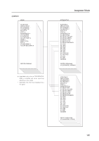
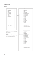
RS-232C Adjustment 5.5 RS-232C Adjustment This display has an RS-232C terminal. It is possible to use a PC to make various adjustments and settings. 5.5.1 About the RS-232C Adjustment Adjustments using the RS-232C: • The adjustments are written to the same memory area as for the integrator mode (refer to section 5.4.4, "PICTURE, White Balance and SCREEN Position Adjustment Values Memory Area Tables" (pg. 184 to 188)). Note (1) Assign an ID before using the RS-232C adjustment. Include the panel ID in the RS-232C command. For details, refer to section 5.5.2, "Interface" (pg. 190). (2) Of the adjustment values and setting items set by RS-232C commands, there are some items that are stored in memory and some that are not. For details, refer to section 5.5.5, "List of RS-232C Commands" (pg. 194). Also, when storing values in "last" memory, the conditions described in section 5.1.5, "Last Memory" (pg. 98), must be satisfied. (3) / (OSD display disable/enable setting) Regardless of the setting, the following items can be displayed. • Menu display (menu mode, integrator mode) • Warnings before Auto Power OFF or Power Management operation • Warning of high temperature inside the panel • Display announcing that the FUNCTIONAL LOCK is set and the FUNCTIONAL LOCK setting display • Display call (including holding a button down) (4) When using RS-232C commands, control the input signal as well as the power. If the power is ON when there is no signal, the display continues to have a weak discharge. This activity can affect the life of the display. 189
-
 1
1 -
2
-
3
-
4
-
5
-
6
-
7
-
8
-
9
-
10
-
11
-
12
-
13
-
14
-
15
-
16
-
17
-
18
-
19
-
20
-
21
-
22
-
23
-
24
-
25
-
26
-
27
-
28
-
29
-
30
-
31
-
32
-
33
-
34
-
35
-
36
-
37
-
38
-
39
-
40
-
41
-
42
-
43
-
44
-
45
-
46
-
47
-
48
-
49
-
50
-
51
-
52
-
53
-
54
-
55
-
56
-
57
-
58
-
59
-
60
-
61
-
62
-
63
-
64
-
65
-
66
-
67
-
68
-
69
-
70
-
71
-
72
-
73
-
74
-
75
-
76
-
77
-
78
-
79
-
80
-
81
-
82
-
83
-
84
-
85
-
86
-
87
-
88
-
89
-
90
-
91
-
92
-
93
-
94
-
95
-
96
-
97
-
98
-
99
-
100
-
101
-
102
-
103
-
104
-
105
-
106
-
107
-
108
-
109
-
110
-
111
-
112
-
113
-
114
-
115
-
116
-
117
-
118
-
119
-
120
-
121
-
122
-
123
-
124
-
125
-
126
-
127
-
128
-
129
-
130
-
131
-
132
-
133
-
134
-
135
-
136
-
137
-
138
-
139
-
140
-
141
-
142
-
143
-
144
-
145
-
146
-
147
-
148
-
149
-
150
-
151
-
152
-
153
-
154
-
155
-
156
-
157
-
158
-
159
-
160
-
161
-
162
-
163
-
164
-
165
-
166
-
167
-
168
-
169
-
170
-
171
-
172
-
173
-
174
-
175
-
176
-
177
-
178
-
179
-
180
-
181
-
182
-
183
-
 184
184 -
 185
185 -
 186
186 -
 187
187 -
 188
188 -
 189
189 -
 190
190 -
 191
191 -
 192
192 -
 193
193 -
 194
194 -
195
-
196
-
197
-
198
-
199
-
200
-
201
-
202
-
203
-
204
-
205
-
206
-
207
-
208
-
209
-
210
-
211
-
212
-
213
-
214
-
215
 |
 |
