Pioneer 607CMX Technical Manual - Page 161
Assigning an ID, The Remote Control ID
 |
UPC - 012562824413
View all Pioneer 607CMX manuals
Add to My Manuals
Save this manual to your list of manuals |
Page 161 highlights
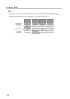
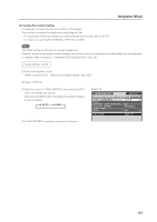
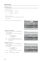
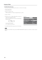
Integrator Mode 13) Assigning an ID This option assigns the ID necessary to adjust only the designated display in a video wall or to make an adjustment using an RS-232C command. For details see "5.5 RS-232C Adjustment" (pg. 189). Factory setting: ALL 1 Enter the integrator mode. (Refer to section 5.4.1, "About the Integrator Mode" (pg. 142).) 2 Select 'OPTION'. 3 Place the cursor on 'ID NO. SET' then press the [SET] button. Screen 3 I N T E G R ATO R INPUT1 PICTURE SCREEN PROGRAM T I MER SCREEN MASK S I DE MASK V I D E O WAL L BAU D R AT E I D NO. SE T SETUP OPTION : GREEN : 1 2 0 0BPS : 01H SET ENTER MENU EXIT 4 Press the [2/3] buttons to change the settings. Each time a [2/3] button is pressed, the setting changes as shown below. 3 ALL 2 3 01H to FFH 2 Screen 4 ALL ID number cannot be set so the panel can be operated from all remote controls. 01H to FFH ... The ID number is set to the designated ID NO. SET SET SET : 01H MENU EXIT number. Display ID numbers may match the ID number that is displayed when the remote control's ID NO. SET button is pressed. The remote control's [ID NO. SET], [CLEAR] buttons are operational. Press the [SET] button to return to screen 3. The 'ID NO. SET' settings are common for all inputs. 7 The Remote Control ID When several Plasma Displays are installed at a single location, it is possible to operate only specified Plasma Displays with the remote control. Set the following options: Factory setting: ALL 1 Register panel ID numbers through the integrator menu. 2 Separately register the ID numbers for remote control use with the [ID NO. SET] button on the remote control. Press the [ID NO. SET] button to display screen 2. Each time a [2/3] button is pressed, the setting changes as shown below. 3 ALL 2 3 01H to FFH 2 Screen 2 ID SELECT POSITION: 1 ID NUMBER : ALL SET SET MENU EXIT 161
-
 1
1 -
2
-
3
-
4
-
5
-
6
-
7
-
8
-
9
-
10
-
11
-
12
-
13
-
14
-
15
-
16
-
17
-
18
-
19
-
20
-
21
-
22
-
23
-
24
-
25
-
26
-
27
-
28
-
29
-
30
-
31
-
32
-
33
-
34
-
35
-
36
-
37
-
38
-
39
-
40
-
41
-
42
-
43
-
44
-
45
-
46
-
47
-
48
-
49
-
50
-
51
-
52
-
53
-
54
-
55
-
56
-
57
-
58
-
59
-
60
-
61
-
62
-
63
-
64
-
65
-
66
-
67
-
68
-
69
-
70
-
71
-
72
-
73
-
74
-
75
-
76
-
77
-
78
-
79
-
80
-
81
-
82
-
83
-
84
-
85
-
86
-
87
-
88
-
89
-
90
-
91
-
92
-
93
-
94
-
95
-
96
-
97
-
98
-
99
-
100
-
101
-
102
-
103
-
104
-
105
-
106
-
107
-
108
-
109
-
110
-
111
-
112
-
113
-
114
-
115
-
116
-
117
-
118
-
119
-
120
-
121
-
122
-
123
-
124
-
125
-
126
-
127
-
128
-
129
-
130
-
131
-
132
-
133
-
134
-
135
-
136
-
137
-
138
-
139
-
140
-
141
-
142
-
143
-
144
-
145
-
146
-
147
-
148
-
149
-
150
-
151
-
152
-
153
-
154
-
155
-
 156
156 -
 157
157 -
 158
158 -
 159
159 -
 160
160 -
 161
161 -
 162
162 -
 163
163 -
 164
164 -
 165
165 -
 166
166 -
167
-
168
-
169
-
170
-
171
-
172
-
173
-
174
-
175
-
176
-
177
-
178
-
179
-
180
-
181
-
182
-
183
-
184
-
185
-
186
-
187
-
188
-
189
-
190
-
191
-
192
-
193
-
194
-
195
-
196
-
197
-
198
-
199
-
200
-
201
-
202
-
203
-
204
-
205
-
206
-
207
-
208
-
209
-
210
-
211
-
212
-
213
-
214
-
215
 |
 |
