Pioneer PDP-425CMX User Manual - Page 12
Part Names and Functions
 |
View all Pioneer PDP-425CMX manuals
Add to My Manuals
Save this manual to your list of manuals |
Page 12 highlights
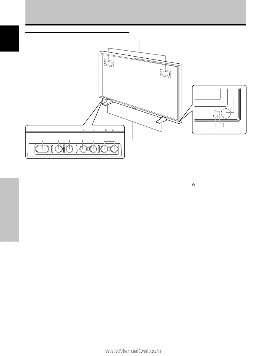
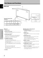
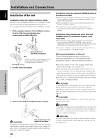
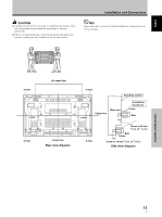
English Part Names and Functions Main unit 5 Main unit Part Names and Functions Operation panel on the main unit STANDBY/ON 6 DISPLAY MENU / SET 78 INPUT SCREEN SIZE - VOL + 90 - 1 STANDBY ON 2 34 Main unit 1 Display stand 2 Remote control sensor Point the remote control toward the remote sensor to operate the unit (page 8). 3 Ambient light sensor This sensor measures the level of light inside the viewing room; it is enabled when the [ENERGY SAVE] option is set to [AUTO] (page 30). 4 STANDBY/ON indicator When the unit is operating: The indicator lights green (page 18). When flashing, the indicator is used to indicate error messages (page 38). The indicator flashes green once every one second when the [POWER MGT.] function is operating (page 23). When the unit is in standby mode: The indicator lights red (page 18). When flashing, the indicator is used to indicate error messages (page 38). 5 Handles Operation panel on the main unit 6 STANDBY/ON button ( ) Press to put the display in operation or standby mode (page 18). 7 MENU button Press to open and close the on-screen menu (pages 16 to 35). 8 DISPLAY/SET button Use to confirm onscreen menu selections, and to change settings (pages 16 to 35). When not indicated by onscreen menus, used to display the current set status (page 19). 9 INPUT (') button Except when menu screen is displayed, this button operates to change the input. 0 SCREEN SIZE (') button Except when menu screen is displayed, this button operates to change the screen size. - VOL +/- (}/]) buttons When not indicated for use in onscreen menu items, these buttons are used for adjusting the sound volume (pages 18 and 19). 6 En
-
 1
1 -
2
-
3
-
4
-
5
-
6
-
 7
7 -
 8
8 -
 9
9 -
 10
10 -
 11
11 -
 12
12 -
 13
13 -
 14
14 -
 15
15 -
 16
16 -
 17
17 -
18
-
19
-
20
-
21
-
22
-
23
-
24
-
25
-
26
-
27
-
28
-
29
-
30
-
31
-
32
-
33
-
34
-
35
-
36
-
37
-
38
-
39
-
40
-
41
-
42
-
43
-
44
-
45
-
46
-
47
-
48
-
49
-
50
-
51
-
52
-
53
-
54
-
55
-
56
-
57
-
58
-
59
-
60
-
61
-
62
-
63
-
64
-
65
-
66
-
67
-
68
-
69
-
70
-
71
-
72
-
73
-
74
-
75
-
76
-
77
-
78
-
79
-
80
-
81
-
82
-
83
-
84
-
85
-
86
-
87
-
88
-
89
-
90
-
91
-
92
-
93
-
94
-
95
-
96
-
97
-
98
 |
 |