Pioneer PDP-425CMX User Manual - Page 23
Settings after connections - 42 in
 |
View all Pioneer PDP-425CMX manuals
Add to My Manuals
Save this manual to your list of manuals |
Page 23 highlights
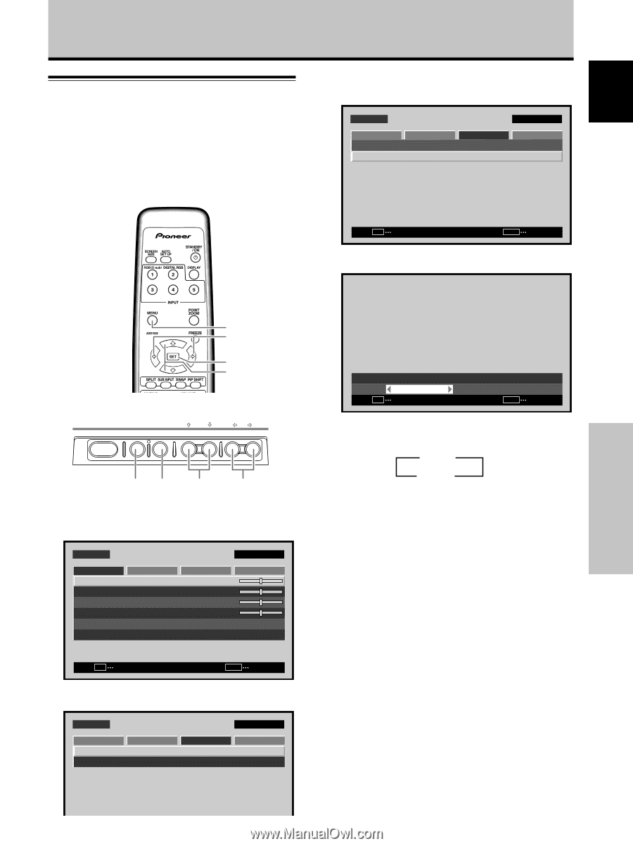
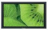
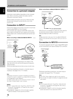
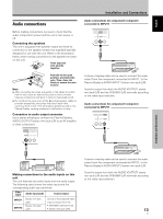
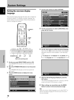
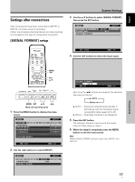
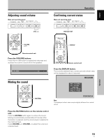
English Settings after connections After components have been connected to INPUT1 or INPUT2, on-screen setup is necessary. Follow the procedure described below and make settings as they apply to the type of components connected. [SIGNAL FORMAT] setup System Settings 3 Use the 5/∞ buttons to select [SIGNAL FORMAT], then press the SET button. MENU PICTURE SCREEN P O W E R M G T. SIGNAL FORMAT INPUT1 SETUP OPTION :OFF SET CHANGE MENU EXIT 4 Use the 2/3 buttons to select the input signal. System Settings MENU 2/3 SET 5/∞ Remote control unit STANDBY/ON DISPLAY MENU / SET INPUT SCREEN SIZE - VOL + MENU SET 5/∞ 2/3 Main unit operating panel 1 Press the MENU button to display the menu screen. MENU PICTURE SCREEN CONTRAST BRIGHTNESS H.ENHANCE V. E N H A N C E SETUP : : : : INPUT1 OPTION 0 0 0 0 PICTURE RESET SET ENTER MENU EXIT 2 Use the 2/3 buttons to select [SETUP]. MENU PICTURE SCREEN P O W E R M G T. SIGNAL FORMAT SETUP :OFF INPUT1 OPTION SIGNAL FORMAT : AUTO SET SET MENU EXIT Each time the 2/3 buttons are pressed, the selection alternates as follows: 3 AUTO Others 2 ÷ AUTO .... Signals are detected automatically in accordance with the Computer signal compatibility table (pages 40 to 42) ÷ Others ... Selectable resolutions are displayed. 5 Press the SET button. The setting is stored in memory and the screen returns to that shown in step 3. 6 When the setup is completed, press the MENU button to exit the menu screen. Note Make [SIGNAL FORMAT] setting for each input (INPUT1 and INPUT2). 17 En
-
 1
1 -
2
-
3
-
4
-
5
-
6
-
7
-
8
-
9
-
10
-
11
-
12
-
13
-
14
-
15
-
16
-
17
-
 18
18 -
 19
19 -
 20
20 -
 21
21 -
 22
22 -
 23
23 -
 24
24 -
 25
25 -
 26
26 -
 27
27 -
 28
28 -
29
-
30
-
31
-
32
-
33
-
34
-
35
-
36
-
37
-
38
-
39
-
40
-
41
-
42
-
43
-
44
-
45
-
46
-
47
-
48
-
49
-
50
-
51
-
52
-
53
-
54
-
55
-
56
-
57
-
58
-
59
-
60
-
61
-
62
-
63
-
64
-
65
-
66
-
67
-
68
-
69
-
70
-
71
-
72
-
73
-
74
-
75
-
76
-
77
-
78
-
79
-
80
-
81
-
82
-
83
-
84
-
85
-
86
-
87
-
88
-
89
-
90
-
91
-
92
-
93
-
94
-
95
-
96
-
97
-
98
 |
 |