Sony DAV X10 Operating Instructions - Page 10
Step 1: Connecting the System and TV, and perform [AUTO CALIBRATION] - speaker cable
 |
View all Sony DAV X10 manuals
Add to My Manuals
Save this manual to your list of manuals |
Page 10 highlights
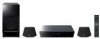
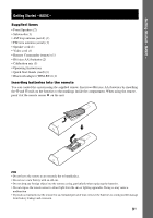
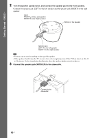
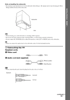
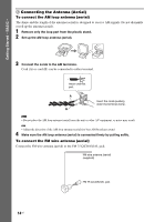
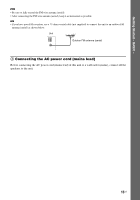
Getting Started - BASIC - Step 1: Connecting the System and TV This hookup is the basic connection of the unit to the speakers and TV. For other TV connections, see page 20. For other component connection, see page 25. To accept progressive signals, see page 23. To obtain the best possible front surround sound, install the speakers in the proper position (page 16), and perform [AUTO CALIBRATION] (page 75). Refer to the connection diagram below, and read the additional information from 1 to 4 on the following pages. Front speaker (R) TV Front speaker (L) AUDIO OUT L R VIDEO IN BA AC power cord (mains lead) OPTICAL TV DIGITAL IN OPTICAL COAXIAL SAT/ CABLE COAXIAL IMPEDANCE USE 4 VIDEO SPEAKER R AUDIO L IN 1 2 DMPORT (DVD COMPONENT VIDEO OUT ONLY) PB / PR / TV Y CB CR (DVD ONLY) OUT ANTENNA VIDEO A.CAL AM MIC ECM-AC2 R AUDIO L VIDEO SAT/CABLE IN R AUDIO L VIDEO VIDEO IN S VIDEO (DVD ONLY) MONITOR OUT FM 75 COAXIAL FM wire antenna (aerial) Subwoofer 10US AM loop antenna (aerial) : Signal flow
-
 1
1 -
2
-
3
-
4
-
 5
5 -
 6
6 -
 7
7 -
 8
8 -
 9
9 -
 10
10 -
 11
11 -
 12
12 -
 13
13 -
 14
14 -
 15
15 -
16
-
17
-
18
-
19
-
20
-
21
-
22
-
23
-
24
-
25
-
26
-
27
-
28
-
29
-
30
-
31
-
32
-
33
-
34
-
35
-
36
-
37
-
38
-
39
-
40
-
41
-
42
-
43
-
44
-
45
-
46
-
47
-
48
-
49
-
50
-
51
-
52
-
53
-
54
-
55
-
56
-
57
-
58
-
59
-
60
-
61
-
62
-
63
-
64
-
65
-
66
-
67
-
68
-
69
-
70
-
71
-
72
-
73
-
74
-
75
-
76
-
77
-
78
-
79
-
80
-
81
-
82
-
83
-
84
-
85
-
86
-
87
-
88
-
89
-
90
-
91
-
92
-
93
-
94
-
95
-
96
-
97
-
98
-
99
-
100
-
101
-
102
-
103
-
104
-
105
-
106
-
107
 |
 |
