Sony DCR-TRV25 Operating Instructions - Page 211
BATT release button, SEL/PUSH EXEC dial, START/STOP button, DC IN jack cover, Intelligent accessory
 |
View all Sony DCR-TRV25 manuals
Add to My Manuals
Save this manual to your list of manuals |
Page 211 highlights
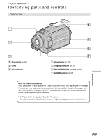
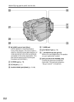
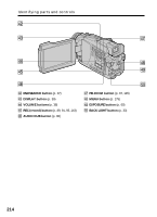
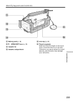
Identifying parts and controls qj wa qk ql w; qj BATT release button (p. 16) qk SEL/PUSH EXEC dial (p. 23) ql START/STOP button (p. 26) w; DC IN jack cover ws wd wf wg wa Intelligent accessory shoe (p. 94) ws LOCK switch* (p. 26) wd POWER switch (p. 17) wf Access lamp* (p. 106) wg "Memory Stick" slot* (p. 106) Notes on the intelligent accessory shoe •The intelligent accessory shoe supplies power to optional accessories such as a video light, microphone or printer.* •The intelligent accessory shoe is linked to the POWER switch, allowing you to turn the power supplied by the shoe on and off. Refer to the operating instructions of the accessory for further information. •The intelligent accessory shoe has a safety device for fixing the installed accessory securely. To connect an accessory, press down and push it to the end, and then tighten the screw. •To remove an accessory, loosen the screw, and then press down and pull out the accessory. * Except DCR-TRV16 Quick Reference 211
-
 1
1 -
2
-
3
-
4
-
5
-
6
-
7
-
8
-
9
-
10
-
11
-
12
-
13
-
14
-
15
-
16
-
17
-
18
-
19
-
20
-
21
-
22
-
23
-
24
-
25
-
26
-
27
-
28
-
29
-
30
-
31
-
32
-
33
-
34
-
35
-
36
-
37
-
38
-
39
-
40
-
41
-
42
-
43
-
44
-
45
-
46
-
47
-
48
-
49
-
50
-
51
-
52
-
53
-
54
-
55
-
56
-
57
-
58
-
59
-
60
-
61
-
62
-
63
-
64
-
65
-
66
-
67
-
68
-
69
-
70
-
71
-
72
-
73
-
74
-
75
-
76
-
77
-
78
-
79
-
80
-
81
-
82
-
83
-
84
-
85
-
86
-
87
-
88
-
89
-
90
-
91
-
92
-
93
-
94
-
95
-
96
-
97
-
98
-
99
-
100
-
101
-
102
-
103
-
104
-
105
-
106
-
107
-
108
-
109
-
110
-
111
-
112
-
113
-
114
-
115
-
116
-
117
-
118
-
119
-
120
-
121
-
122
-
123
-
124
-
125
-
126
-
127
-
128
-
129
-
130
-
131
-
132
-
133
-
134
-
135
-
136
-
137
-
138
-
139
-
140
-
141
-
142
-
143
-
144
-
145
-
146
-
147
-
148
-
149
-
150
-
151
-
152
-
153
-
154
-
155
-
156
-
157
-
158
-
159
-
160
-
161
-
162
-
163
-
164
-
165
-
166
-
167
-
168
-
169
-
170
-
171
-
172
-
173
-
174
-
175
-
176
-
177
-
178
-
179
-
180
-
181
-
182
-
183
-
184
-
185
-
186
-
187
-
188
-
189
-
190
-
191
-
192
-
193
-
194
-
195
-
196
-
197
-
198
-
199
-
200
-
201
-
202
-
203
-
204
-
205
-
 206
206 -
 207
207 -
 208
208 -
 209
209 -
 210
210 -
 211
211 -
 212
212 -
 213
213 -
 214
214 -
 215
215 -
 216
216 -
217
-
218
-
219
-
220
 |
 |
