Sony FWD-32LX1R Operating Instructions - Page 7
Location and Function, of Parts and Controls - stand
 |
View all Sony FWD-32LX1R manuals
Add to My Manuals
Save this manual to your list of manuals |
Page 7 highlights
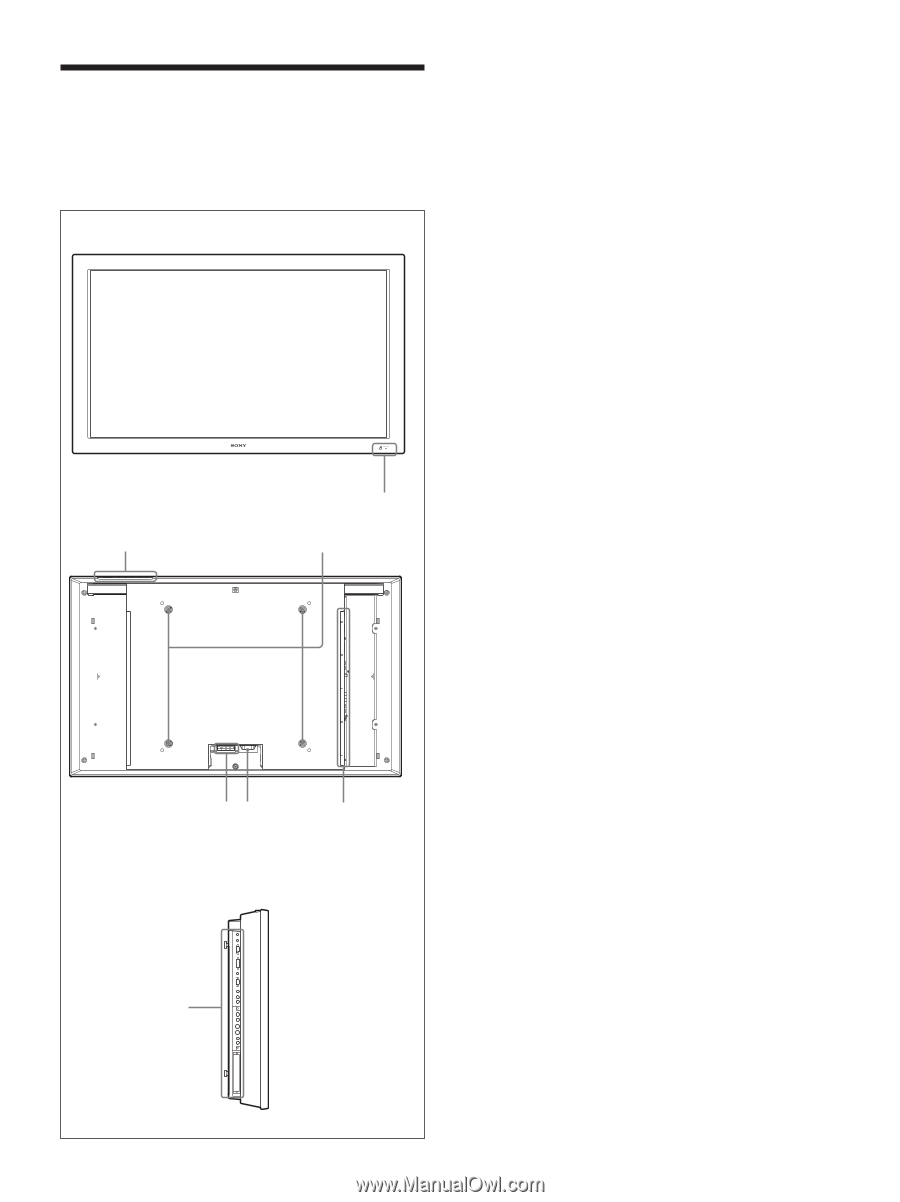
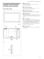
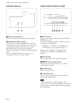
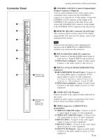
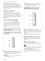
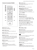
Location and Function of Parts and Controls Front / Rear / Side Front Rear 2 1 3 Location and Function of Parts and Controls 1 Indicator section For details on the Indicator section, see "Indicator Section" on page 8 (GB). 2 Control button section For details on the control button section, see "Control Button Section (Top)" on page 8 (GB). 3 Stand installation hooks Use these hooks to install the stand (not supplied). 4 SPEAKER Socket Connects the speakers (not supplied) to this socket to output the audio matching the signal displayed on the screen. 5 - AC IN socket Connect the supplied AC power cord to this socket and to a wall outlet. Once you connect the AC power cord, the POWER/STANDBY indicator lights up in red and the display goes into the standby mode. For more details on the power cord, see "Connecting the AC Power Cord" on page 14 (GB). 6 Connector panel For details on the connector panel, see "Connector Panel" on page 9 (GB). 45 6 Side 6 7 (GB)
-
 1
1 -
 2
2 -
 3
3 -
 4
4 -
 5
5 -
 6
6 -
 7
7 -
 8
8 -
 9
9 -
 10
10 -
 11
11 -
 12
12 -
13
-
14
-
15
-
16
-
17
-
18
-
19
-
20
-
21
-
22
-
23
-
24
-
25
-
26
-
27
-
28
-
29
-
30
-
31
-
32
-
33
-
34
-
35
-
36
-
37
-
38
-
39
-
40
-
41
-
42
-
43
-
44
-
45
 |
 |