Sony FWDS42H1 Operating Instructions - Page 57
Parts, Description, Ac In, Speaker, Power, Input, Enter, Return, Remote, Audio - speakers
 |
UPC - 027242754423
View all Sony FWDS42H1 manuals
Add to My Manuals
Save this manual to your list of manuals |
Page 57 highlights
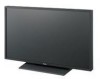
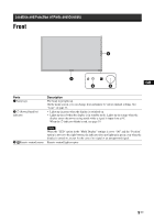
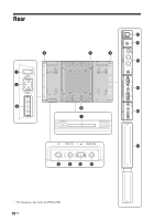
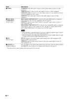
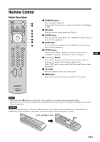
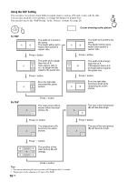
Parts 1 Main power switch 2 AC IN socket 3 SPEAKER socket 4 Speaker installation positions 5 Stand installation holes 6 Applicable display stand installation holes 7 Dedicated display stand installation hole cover 8 1 (POWER) switch 9 INPUT/ (ENTER)button 0 +/-/F/f (volume/cursor) button qa MENU/ (RETURN) button qs REMOTE (10BASE-T/100BASE-TX) qd AUDIO (Stereo mini jack) Description Turn the main power switch to "ON"(press the side) when setting up the device. When the main power switch is turned "OFF" (press the side), the power consumption is 0W. Connect the supplied AC power cord to this socket and to a wall outlet. See page 19. Once you connect the AC power cord and turn on main power switch, the 1 indicator lights up in red and the display goes into the standby mode. Connect the speakers SS-SPG01 (not supplied) to this socket. For more details on connecting the speakers, see the operating manual that came with the speakers. For details on how to route the speaker cords, see page 20. Attach the dedicated speakers SS-SPG01. Screw holes conforming to VESA standard. (Pitch: 400mm × 400mm, Screw: M6) Use these hooks to install the display stand SU-S01 (not supplied). Remove when mounting the display stand SU-S01 (not supplied). Switches the display on or off (standby). Operate when the main power switch is "ON" ( side). Press to select a signal to be input from the INPUT or OPTION connector. The signal to be input switches as follows each time you press the INPUT button. S Video Video HD15 DVI OPTION When an optional adaptor supporting the video signal is not installed in the OPTION slot, OPTION will be skipped. Press to set your choice. Press to control speaker volume. When the menu is displayed, press to move the cursor or set a value. Press to set your choice. Press to show menus. This returns to the preceding menu screen. Serves to connect the display to a network, using a 10BASE-T/100BASE-TX LAN cable. You can assign various settings and control the display via the network from a PC. Cautions • When you connect the LAN cable of the unit to peripheral device, use the supplied cable to prevent malfunction due to radiation noise. • For safety, do not connect the connector for peripheral device wiring that might have excessive voltage to this port. Follow the instructions for this port. Note When using this connector, select "Display" in "Network Port". (page 32) This is the audio monitor output terminal for external devices. Outputs an audio of the signal currently indicated on the screen. Outputs an audio signal corresponding to the active* picture while in the "P&P" or "PinP" mode. Note • Settings assigned in "Sound Mode" or "Speaker Out" will not be reflected. • The noise reduction status set by the remote control is not reflected. GB 11 GB
-
 1
1 -
2
-
3
-
4
-
5
-
6
-
7
-
8
-
9
-
10
-
11
-
12
-
13
-
14
-
15
-
16
-
17
-
18
-
19
-
20
-
21
-
22
-
23
-
24
-
25
-
26
-
27
-
28
-
29
-
30
-
31
-
32
-
33
-
34
-
35
-
36
-
37
-
38
-
39
-
40
-
41
-
42
-
43
-
44
-
45
-
46
-
47
-
48
-
49
-
50
-
51
-
 52
52 -
 53
53 -
 54
54 -
 55
55 -
 56
56 -
 57
57 -
 58
58 -
 59
59 -
 60
60 -
 61
61 -
 62
62 -
63
-
64
-
65
-
66
-
67
-
68
-
69
-
70
-
71
-
72
-
73
-
74
-
75
-
76
-
77
-
78
-
79
-
80
-
81
-
82
-
83
-
84
-
85
-
86
-
87
-
88
-
89
-
90
-
91
-
92
-
93
-
94
-
95
-
96
-
97
-
98
-
99
-
100
-
101
-
102
-
103
-
104
-
105
-
106
-
107
-
108
-
109
-
110
-
111
-
112
-
113
-
114
-
115
-
116
-
117
-
118
-
119
-
120
-
121
-
122
-
123
-
124
-
125
-
126
-
127
-
128
-
129
-
130
-
131
-
132
-
133
-
134
-
135
-
136
-
137
-
138
-
139
-
140
-
141
-
142
-
143
-
144
-
145
-
146
-
147
-
148
-
149
-
150
-
151
-
152
-
153
-
154
-
155
-
156
-
157
-
158
-
159
-
160
-
161
-
162
-
163
-
164
-
165
-
166
-
167
-
168
-
169
-
170
-
171
-
172
-
173
-
174
-
175
-
176
-
177
-
178
-
179
-
180
-
181
-
182
-
183
-
184
-
185
-
186
-
187
-
188
-
189
-
190
-
191
-
192
-
193
-
194
-
195
-
196
-
197
-
198
-
199
-
200
-
201
-
202
-
203
-
204
-
205
-
206
-
207
-
208
-
209
-
210
-
211
-
212
-
213
-
214
-
215
-
216
-
217
-
218
-
219
-
220
-
221
-
222
-
223
-
224
-
225
-
226
-
227
-
228
-
229
-
230
-
231
-
232
-
233
-
234
-
235
-
236
-
237
-
238
-
239
-
240
-
241
-
242
-
243
-
244
-
245
-
246
-
247
-
248
-
249
-
250
-
251
-
252
-
253
-
254
-
255
-
256
-
257
-
258
-
259
-
260
-
261
-
262
-
263
-
264
-
265
-
266
-
267
-
268
-
269
-
270
-
271
-
272
-
273
-
274
-
275
-
276
-
277
-
278
-
279
-
280
-
281
-
282
-
283
-
284
-
285
-
286
-
287
-
288
-
289
-
290
-
291
-
292
-
293
-
294
-
295
-
296
-
297
-
298
-
299
-
300
-
301
-
302
-
303
 |
 |