Sony HDWM2000/20 Operation Manual
Sony HDWM2000/20 Manual
 |
View all Sony HDWM2000/20 manuals
Add to My Manuals
Save this manual to your list of manuals |
Sony HDWM2000/20 manual content summary:
- Sony HDWM2000/20 | Operation Manual - Page 1
HD DIGITAL VIDEOCASSETTE RECORDER HDW-2000 HDW-M2000 HDW-M2000P OPERATION MANUAL [English] 1st Edition (Revised 6) - Sony HDWM2000/20 | Operation Manual - Page 2
or moisture. To avoid electrical shock, do not open the cabinet. Refer servicing to qualified personnel only. THIS APPARATUS MUST BE EARTHED. AVERTISSEMENT Afin d'éviter , uses, and can radiate radio frequency energy and, if not installed and used in accordance with the instruction manual, - Sony HDWM2000/20 | Operation Manual - Page 3
approved Power Cord (3-core mains)/Appliance Connector/Plug with earthing-contacts that conforms to the safety regulations of each country if applicable. 2. Use the Power Cord (3-core mains lead)/Plug conforming to the following ratings, which meets power supply voltage of each country. Rating: 10A - Sony HDWM2000/20 | Operation Manual - Page 4
- Sony HDWM2000/20 | Operation Manual - Page 5
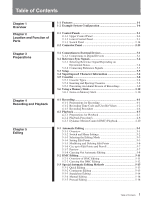
Ejecting Cassettes 3-8 3-5-3 Preventing Accidental Erasure of Recordings 3-9 3-6 Using a Memory Stick 3-10 3-6-1 Notes on Memory Stick 3-10 Quick Editing 5-13 5-3-2 Continuous Editing 5-13 5-3-3 Standalone Editing 5-14 5-3-4 Manual Editing 5-14 5-3-5 Preread Editing 5-14 1 Table of Contents - Sony HDWM2000/20 | Operation Manual - Page 6
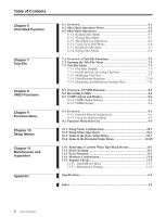
of Tele-File Functions 7-1 7-2 Opening the Tele-File Menu 7-2 7-3 Tele-File Menu 7-3 7-3-1 Clip Data Display 7-3 7-3-2 Preroll and Cue Up Using Clip Data 7-6 7-3-3 Modifying Clip Data 7-7 7-3-4 Undo/Resume Functions 7-10 7-3-5 Displaying and Modifying Attribute Data 7-11 8-1 Overview of UMID - Sony HDWM2000/20 | Operation Manual - Page 7
HDW-2000/M2000/M2000P is a high-definition (HD) digital videocassette recorder based on the HDCAM format. This unit uses HDCAM video/ audio data) (Option) • Time code input/output • CUE audio input/output High quality four-channel audio High quality 20 bit/48 kHz AES/EBU digital audio is supported - Sony HDWM2000/20 | Operation Manual - Page 8
, but also the pages of a menu system for commonly used functions. You can use the function keys and MULTI CONTROL knob to easily change settings even while playing back an HDCAM format tape. Upward converter function (HDW-M2000/ M2000P only) The HDW-M2000/M2000P features a standard definition to - Sony HDWM2000/20 | Operation Manual - Page 9
you can also control a number of VTRs simultaneously. Additionally, a parallel (50-pin) interface is also fitted as standard, supporting easy external control through the parallel interface. Rack mounting Using the optional RMM-131 Rack Mount Adaptor, you can mount the unit in a standard EIA 19-inch - Sony HDWM2000/20 | Operation Manual - Page 10
Chapter 1 Overview 1-11 -F2eaEtuxreasmple System Configuration The following conceptual diagram shows an example of use. Digital cassette BVE-series editor Tape control HDW-2000/M2000/M2000P SDTI (optional) HDSDI Audio/video server system HDSDI/Analog composite Video monitor Audio monitor - Sony HDWM2000/20 | Operation Manual - Page 11
Chapter 2 LocaCthiaoptenr 2 and Location Fandunct Functioniofon of Parts Parts 2-1 Control Panels There are three control panels, as follows: • Upper control panel • Lower control panel • Switch panel Z 59.94 VID. IN PB/EE CONFI CTL/TC MENU TCGSET SDI EE DISABL TC Upper control panel (see - Sony HDWM2000/20 | Operation Manual - Page 12
button. While the cassette is being ejected, this button lights. When using the lower control panel as remote control panel, press the DELETE button (BETACAM/SP, BETACAM SX, MPEG IMX, Digital BETACAM, or HDCAM) corresponding to the current recording or playback format lights. The BETACAM Manual. - Sony HDWM2000/20 | Operation Manual - Page 13
Chapter 2 Location and Function of Parts 2-1-2 Lower Control Panel 4 Time data/menu display section (see page 2-7) 2 CHANNEL CONDITION indicator (see page 2-6) 1 Audio control section (see page 2-4) 3 Menu control buttons (see page 2-6) 5 MULTI CONTROL knob and PUSH/ SHIFT indicator (see page - Sony HDWM2000/20 | Operation Manual - Page 14
channel (HDSDI, SDTI, AES/EBU, or ANA). In this state, you can use the audio monitor signal selection buttons to select the signal to input to each covers the range -60 dB to 0 dB or -40 dB to +20 dB as selected using setup menu item 806. In this mode the segment of the display corresponding to - Sony HDWM2000/20 | Operation Manual - Page 15
signal level when the unit is in recording or playback mode. You can use the setup menu to switch the display mode between PEAK.0 (0 dB is maximum level) and REF.0 (0 dB is the reference level). You can also use the DISPLAY FULL/FINE button 2 to enlarge the display only near the reference - Sony HDWM2000/20 | Operation Manual - Page 16
internal inspection is necessary. 3 Menu control buttons These buttons are used for function menu (see the following section "Overview of the function the function menu The function menu provides convenient access to frequently used function settings, such as input video signal selection and time - Sony HDWM2000/20 | Operation Manual - Page 17
to 1080 line standard format signals. DB 1035: Signals recorded in Digital Betacam format are output after conversion to 1035 line standard format signals. 1035t1080: HDCAM signals recorded in 1035 line standard format are output after conversion to 1080 line standard signals. HD 1080 - Sony HDWM2000/20 | Operation Manual - Page 18
JOG VAR FORWARD 4 SHUTTLE/VAR and JOG indicators 5 Search dial ... 1) CONFI playback: This refers to playback of the audio and video signals immediately after recording, using the confidence heads, the signal being output to all intents and purposes simultaneously with recording. This is - Sony HDWM2000/20 | Operation Manual - Page 19
see the description of the search dial 5. 3 VAR (variable) button To use the search dial for playback in variable speed mode, press this button, turning by the position of the search dial. Playback speed ranges are as follows. • HDCAM tape: ±50 times normal speed (59.94i, 29.97PsF mode), ±58 times - Sony HDWM2000/20 | Operation Manual - Page 20
unit at the end of preroll ("stop mode" 1) or still playback mode) using setup menu item 001 or 401. Cuing up edit points Hold down the In this case the button does not light. 3 EDIT button To carry out manual editing, press this button simultaneously with the PLAY button. Monitoring in E-E mode - Sony HDWM2000/20 | Operation Manual - Page 21
on audio channels 1 to 8. CUE button: Selects the cue audio signal. Note When the ASSEMBLE button is lit, none of the INSERT buttons work. To use INSERT buttons, press the ASSEMBLE button, turning it off. ... 1) Assemble editing: Editing in which new video/audio is added in sequence to the end of - Sony HDWM2000/20 | Operation Manual - Page 22
an error message appears in the time data/menu display section. If you are using the HDSDI OUTPUT 3 (SUPER), SDI OUTPUT 3 (SUPER) or COMPOSITE VIDEO For details on error messages, refer to Section 1-24 in the Maintenance Manual Volume 1. KEY INHI (inhibit) indicator This indicator lights when the KEY - Sony HDWM2000/20 | Operation Manual - Page 23
IN point or audio OUT point set in time data display area 2. ENTRY button Use this for setting edit points and so on. • To set a video IN GOOD SHOT MARK REC/ ERASE 2 REC/ERASE indicator 3 MARK button 1 LIST button Use this button to read in and list shot marks. 2 REC/ERASE indicator This lights in - Sony HDWM2000/20 | Operation Manual - Page 24
on firmware update and setup menu reading/ storing, refer to the Maintenance Manual Volume 1. 2 Memory card ejection button Press to eject a memory card control panels are connected to the unit, the PANEL SELECT switch is used to specify which panel be enabled to control the unit. FRONT: Enables - Sony HDWM2000/20 | Operation Manual - Page 25
and impedance Switch setting Level Impedance -60 dBu High impedance LOW-OFF (microphone input) (approx. 20 kΩ) (left position) +4 dBu High impedance HIGH-OFF (line audio input) (approx. 20 kΩ) (center position) +4 dBm 600Ω (line audio input) HIGH-ON 600Ω (right position) 3 AUDIO OUTPUT - Sony HDWM2000/20 | Operation Manual - Page 26
with chroma burst (VBS) or a monochrome video signal (VS). When using the loop-through connection set the switch to the OFF position, and otherwise CH7/8) of AES/EBU format digital audio signals. However, the HDW-2000 supports 2 sets only (4 channels: CH1/2, CH3/4). 2-16 Chapter 2 Location and - Sony HDWM2000/20 | Operation Manual - Page 27
Data Transport Interface) OUTPUT connectors (BNC type) Output SDTI format video and audio signals. 1 AC IN connector 2 Ground terminal 1 AC IN connector Use the optional power cord to connect this to an AC outlet. 2 Ground terminal Connect this to ground. 6 External device connectors REMOTE - Sony HDWM2000/20 | Operation Manual - Page 28
signals from an external device. For details, refer to the Installation Manual. 2 CONTROL PANEL connector (round type, 10pin) In addition to the ) connector (D-sub 9-pin) When using this unit together with another HDCAM VTR, and a BVE-series BVE-700/900/910/2000/9000/ 9000P/9100/9100P or other - Sony HDWM2000/20 | Operation Manual - Page 29
Chapter 2 Location and Function of Parts 1 MONITOR OUTPUT R connector (XLR 3-pin, male) This outputs the audio signals whose output destination was set to 'R' with the audio monitor signal selection buttons in the audio control section. If multiple tracks have been set to 'R', the signals of those - Sony HDWM2000/20 | Operation Manual - Page 30
- Sony HDWM2000/20 | Operation Manual - Page 31
, with this unit used as recorder. Reference signal 75 Ω termination switch: OFF REF. VIDEO INPUT HDSDI OUTPUT 75Ω REF. VIDEO INPUT HDW-M2100/M2100P (player) 75Ω termination switch: ON REF. VIDEO INPUT 75Ω REMOTE 1-IN(9P) REMOTE 1-OUT(9P) HDSDI INPUT HDW-2000/M2000/M2000P (recorder) SDI - Sony HDWM2000/20 | Operation Manual - Page 32
3-2 Reference Sync Signals Chapter 3 Preparations This section describes how reference signals for the video output signals and servo system are selected. The output from the internal reference video signal generator is supplied to the output video signal and servo circuits as a reference signal. - Sony HDWM2000/20 | Operation Manual - Page 33
in which the unit is to be used. • Connections for recording from a switcher or signal generator Reference signal Switcher or signal generator 75 Ω termination switch: ON REF. VIDEO INPUT HDSDI INPUT 75Ω Chapter 3 Preparations HDW-2000/M2000/M2000P • Connections for recording from an external - Sony HDWM2000/20 | Operation Manual - Page 34
3-2 Reference Sync Signals • Connections for playback SD video monitor 75 Ω termination switch: ON • SDI OUTPUT • COMPOSITE • COMPONENT 75Ω HD video monitor HDSDI OUTPUT REF. VIDEO INPUT HDW-2000/M2000/M2000P Reference signal Chapter 3 Preparations 3-4 Chapter 3 Preparations - Sony HDWM2000/20 | Operation Manual - Page 35
page 11-5). This unit allows menu settings to be saved in what are termed "menu banks". Saved sets of menu settings can be recalled for use as required. For more information about the menu banks, see the section "Menu bank operations (menu items B01 to B13)" (page 10-5) . 3-5 Chapter 3 Preparations - Sony HDWM2000/20 | Operation Manual - Page 36
menu settings, and alarm messages. Information displayed Adjusting the character display You can adjust the position, size and type of the superimposed characters using setup menu items 002, 003, 005, 009, and 011. For details, see Section 10-3 "Items in the Basic Setup Menu" (page 10-7). Chapter - Sony HDWM2000/20 | Operation Manual - Page 37
Chapter 3 Preparations 2 Time code reader drop frame mark (for 59.94i, 29.97PsF mode only) ".": Indicates drop frame mode ":": Indicates non-drop-frame mode 3 Time code generator drop frame mark (for 59.94i, 29.97PsF mode only) ".": Indicates drop frame mode (factory preset) ":": Indicates non-drop - Sony HDWM2000/20 | Operation Manual - Page 38
uses the following HDCAM cassettes for both recording and playback. HDCAM cassettes Small cassettes BCT-6HD/12HD/22HD/32HD/40HD Large cassettes BCT-34HDL/64HDL/94HDL/124HDL The HDW-M2000/M2000P 1-17 in the Installation Manual. STANDBY REW PLAY F FWD STOP Large cassette STANDBY button STOP button - Sony HDWM2000/20 | Operation Manual - Page 39
Chapter 3 Preparations 3-5-3 Preventing Accidental Erasure of Recordings To prevent a tape from being inadvertently erased, press in the red record inhibit plug on the cassette. Large cassette Small cassette Press in the red record inhibit plug. ("ON") Return this plug to its original position to - Sony HDWM2000/20 | Operation Manual - Page 40
stored on the Memory Stick, which enables you to share data among cameras. Note Use a Memory Stick formatted with this VTR. It cannot be shared with other devices. For more details, refer to the Maintenance Manual. Inserting a Memory Stick Insert a Memory Stick with the label side up into the Memory - Sony HDWM2000/20 | Operation Manual - Page 41
or modify a Memory Stick. • Do not let the Memory Stick get wet. • Do not use or keep a Memory Stick in locations that are: - Extremely hot such as in a car parked Maintenance Manual. Memory Stick and are the trademarks of Sony Corporation. MagicGate Memory Stick and are the trademarks of - Sony HDWM2000/20 | Operation Manual - Page 42
- Sony HDWM2000/20 | Operation Manual - Page 43
Chapter 4 Recording and PlayCbhaaptecr 4k Recording and Playback 4-1 Recording This section describes video and audio recording on the unit. 4-1-1 Preparations for Recording Switch and menu settings Before beginning recording, make necessary switch and menu settings. For details on each setting, - Sony HDWM2000/20 | Operation Manual - Page 44
at a preset reference level (a reference -20 dB indication for an input of +4 dBm). Manually adjusting the recording levels For each channel possible to simultaneously monitor the video and audio signals being recorded. To use the emphasis function To add emphasis to the analog input audio signal or - Sony HDWM2000/20 | Operation Manual - Page 45
code track provide for eight hexadecimal digits, which can be used to hold the date, time, or other information. Use the following procedure. 1 Set the CTL/TC to UB. bits are overwritten with the shot mark data for 20 frames from the start of recording in crash record mode, assemble edit mode, - Sony HDWM2000/20 | Operation Manual - Page 46
unit To synchronize the internal time code generator to an external signal, use the following procedure. Z • To synchronize to LTC data contained in setting PR/ RGN (F2) to LTC. 4-1-3 Recording Procedure To record, use the following procedure. Z TIME CODE IN OUT 1 1,2 TIME CODE IN connector - Sony HDWM2000/20 | Operation Manual - Page 47
Chapter 4 Recording and Playback 4-2 Playback This section describes playback of video and audio. 4-2-1 Preparations for Playback Switch and menu settings Before beginning playback, make necessary switch and menu settings. For details on each setting, see the pages indicated in parenthesis. - Sony HDWM2000/20 | Operation Manual - Page 48
• Playback in variable speed mode Variable speed playback, with the speed finely determined by the angular position of the search dial • Playback using the capstan override function The playback speed is adjusted temporarily according to the angular position of the search dial, to align the playback - Sony HDWM2000/20 | Operation Manual - Page 49
of setup menu item 116. To carry out playback in jog mode, use the following procedure. Z Playback in shuttle mode In shuttle mode, you can angular position of the search dial. The range of playback speed is as follows. • HDCAM tape: ±50 times normal speed (59.94i, 29.97PsF mode), ±58 times normal - Sony HDWM2000/20 | Operation Manual - Page 50
variable speed mode, you can finely control playback speed within the following ranges: • HDCAM: -1 to +2 times normal speed • Digital Betacam : -1 to +3 times variable speed mode, use the following procedure. Playback using the capstan override function You can use the capstan override function - Sony HDWM2000/20 | Operation Manual - Page 51
Chapter 4 Recording and Playback To perform continuous capstan override playback Z 3 2 1 Set setup menu item 111 (TSO PLAY) to TSO. 2 Hold down the DMC EDIT button and turn the MULTI CONTROL knob to select the playback speed. The selected playback speed is displayed in time data display area 2 - Sony HDWM2000/20 | Operation Manual - Page 52
Normal speed playback DMC playback Normal speed playback Storing a varying playback speed in memory To store the playback speed for DMC playback, use the following procedure. Z 1 Press the DMC EDIT button, turning it on. 2 Either while playing back the recorded tape, or during recording, press - Sony HDWM2000/20 | Operation Manual - Page 53
. Operate the search dial as required, to adjust the playback speed. 1,2 To start playback at the on-air cue from the on-air start point Use the following procedure. 1 Press the REVIEW button. The REVIEW button lights, and the tape is cued up to the on-air start point. After the - Sony HDWM2000/20 | Operation Manual - Page 54
Chapter 4 Recording and Playback 4-2 Playback To start playback immediately after preroll Press the PREVIEW button. The PREVIEW button lights, and after preroll, DMC playback is carried out for the section from the speed variation start point, then playback continues at normal speed from the speed - Sony HDWM2000/20 | Operation Manual - Page 55
(page 5-8) Checking the editing results as necessary (page 5-9) Using an editing control unit When controlling this unit with an editing control unit, set an edit delay on the editing control unit so that cut in and cut out instructions are output 5 frames before the actual edit point. 5-1 Chapter - Sony HDWM2000/20 | Operation Manual - Page 56
5-1 Automatic Editing 5-1-2 Switch and Menu Settings Before beginning editing, make necessary switch and menu settings. Recorder settings POWER switch: 'I' side (on) REMOTE buttons (see page 2-2): 1(9P) ASSEMBLE button (see page 2-11): lit Z 59.94 VID. IN PB/EE CONFI CTL/TC MENU TCGSET SDI EE - Sony HDWM2000/20 | Operation Manual - Page 57
. 5-1-4 Setting Edit Points Set the edit points (IN and OUT points). To use split editing in insert mode, you can set the audio and video edit points IN and OUT points and the player IN and OUT points have been set. Use the DELETE button to delete a redundant edit point, or set the edit points - Sony HDWM2000/20 | Operation Manual - Page 58
indicate that such a setup is impossible. Delete all unnecessary edit points, using the DELETE button. For details of how to delete edit points, see can be deleted or corrected later regardless of whether it was set manually or automatically. Audio IN point Recorder IN point Audio OUT point OUT - Sony HDWM2000/20 | Operation Manual - Page 59
to set separate audio and video edit points on the VTR you are using as the player, you can carry out split editing by setting the audio data display area 2, thus: "DURATION 0:01:10:00". To display a duration, use the following procedure. 1 Press the RECORDER button or PLAYER button to select the VTR - Sony HDWM2000/20 | Operation Manual - Page 60
case, either modify the erroneous edit point, or first delete it and then enter it correctly. Deleting an edit point To delete an edit point, use the following procedure. You can use the same procedure whether or not the DELETE button is flashing. Z Modifying an edit point To modify an edit point - Sony HDWM2000/20 | Operation Manual - Page 61
, indicating that you can carry out a preview. To carry out a preview, use the following procedure. Z Z Chapter 5 Editing 21 1 Press the RECORDER button The factory default setting for the preroll time is 5 seconds, but you can use menu item 001 to change this to any value from 0 to 30 seconds. - Sony HDWM2000/20 | Operation Manual - Page 62
5-1 Automatic Editing Monitor output During a preview, on a monitor connected to the recorder you can monitor the following video and audio. • From the preroll point to the IN point, you can monitor the playback from the recorder. • From the IN point to the OUT point, you can monitor the playback - Sony HDWM2000/20 | Operation Manual - Page 63
single monitor for video and audio on both player and recorder For efficient editing if only one monitor is available, use the following method. 1 Connect the monitor to the recorder. 2 In the basic setup menu, set item 008 to AUTO. 3 Press the PLAYER button on the - Sony HDWM2000/20 | Operation Manual - Page 64
Chapter 5 Editing 5-1 Automatic Editing After automatic editing, to adjust the edit points and reexecute the edit Hold down the DELETE button and press the ENTRY button to recall the edit points. After adjusting the edit points, press the AUTO EDIT button to carry out the edit again. For details of - Sony HDWM2000/20 | Operation Manual - Page 65
playback speed from the recorder, you can achieve variable speed editing. 5-2-1 Overview of DMC Editing Conditions for DMC editing DMC editing can be used for insert or assemble editing, but not for audio split editing. Tape movement during DMC editing The following figure illustrates how the tapes - Sony HDWM2000/20 | Operation Manual - Page 66
Chapter 5 Editing 5-2 DMC Editing 5-2-2 Carrying Out DMC Editing Setting the edit points and player speed Use the following procedure. Z 2,6,7 8 4 1 5 3 6,9 1 Press the ASSEMBLE button or the desired INSERT button to select the editing mode. 2 Press the DMC EDIT button. This unit switches - Sony HDWM2000/20 | Operation Manual - Page 67
• Quick editing • Continuous editing • Standalone editing • Manual editing • Preread editing 5-3-1 Quick Editing After selecting the PREVIEW button. After automatic editing of one edit segment, to carry out continuous editing use the following procedure. 1 Set the player IN and OUT points. On the - Sony HDWM2000/20 | Operation Manual - Page 68
to carry out automatic editing. If necessary, you can also first set the OUT point. 5-3-4 Manual Editing Use the following procedure to carry out manual editing. 1 Press the RECORDER button, turning it on. 2 Use the search dial in jog or shuttle mode to find the editing start point (the recorder IN - Sony HDWM2000/20 | Operation Manual - Page 69
Notes • In preread editing, if an input video signal is used as the reference signal for the output video signal, this forms set item 309 in the extended setup menu to AUTO1 (see page 10-15) so as to use an external reference signal. • When the preread mode is selected, to prevent feedback due to the - Sony HDWM2000/20 | Operation Manual - Page 70
- Sony HDWM2000/20 | Operation Manual - Page 71
use shot marks at desired points on a tape which enable faster cuing. recorded on HDCAM tape. Shot marks are indications Types of shot mark This unit supports Shot mark 1 and shot mark 2 Post mark Written by a manual shot mark operation during recording or editing. Not written (Written only by - Sony HDWM2000/20 | Operation Manual - Page 72
6-2 Shot Mark Operation Menu This section describes the settings in the shot mark operation menu. Displaying the shot mark operation menu With the function menu HOME page showing in the menu display, hold down the MARK button, and press the F5 (MENU) button. Z F5 (MENU) button MARK button The - Sony HDWM2000/20 | Operation Manual - Page 73
written on the tape each time you start recording in that mode. Note When using insert mode, press the TC button to turn the indicator on. Writing shot mark), then the user bits are overwritten with the shot mark data for 20 frames from the start of recording in crash record mode, assemble edit mode - Sony HDWM2000/20 | Operation Manual - Page 74
6-3 Shot Mark Operations To write in crash recording or assemble editing 1 Hold the MARK button down for at least 2 seconds. 2 At the position you wish to write the mark, hold down the ENTRY button, and press the MARK button. A mark of the type selected in item G04 of the shot mark operation menu - Sony HDWM2000/20 | Operation Manual - Page 75
. In item G02 of the shot mark operation menu, set the required types to "ON". For details of the menu, see page 6-2. You can also use the following procedure to specify whether shot marks that have been read are displayed or not. 1 With the shot mark list displayed, press the F5 - Sony HDWM2000/20 | Operation Manual - Page 76
to turn off the REC/ERASE indicator. 6-3-4 Cuing Up to Shot Marks Cuing up to a selected shot mark Use the following procedure. Z Erasing shot marks from the tape To erase a shot mark, use the following procedure. Note Once you erase a shot mark from the tape, it cannot be read back in. 6-6 Chapter - Sony HDWM2000/20 | Operation Manual - Page 77
menu page 4 (page 9-7) and setup menu item 005 (page 10-7). Note You cannot use the above procedure to cue up to a virtual shot mark. The tape is played back in the shot data depend on the shooting conditions. If because of the devices used there is no shot data on a part of the tape, it appears as - Sony HDWM2000/20 | Operation Manual - Page 78
data recorded on the tape, you can separate the shot marks by cassette, and sort them in time code sequence. To sort the shot marks Use the following procedure. Z 23 1 1 With the shot mark list displayed, press the F5 (SETING) button. 2 Press the F2 (NEXT) button, and select SORTING LIST. 3 Press - Sony HDWM2000/20 | Operation Manual - Page 79
writing authorization can be controlled through multiple passwords and permission settings. Data library management with handy reader/writer An optional handy reader/writer (supporting Memory Stick) is available to facilitate data library management. Chapter 7 Tele-File 7-1 Chapter 7 Tele-File - Sony HDWM2000/20 | Operation Manual - Page 80
7-2 Opening the Tele-File Menu Opening from the function menu Configuration of the Tele-File menu Display page 5 of the function menu in the menu display section, and then press the F1 (TELE-F) button. The Tele-File menu opens. For details about the function menu, see Chapter 9 "Function Menu" ( - Sony HDWM2000/20 | Operation Manual - Page 81
7-3 Tele-File Menu 7-3-1 Clip Data Display How to read the display Shown below are examples of the default menu displays in the menu display section and the monitor display. For more information about how to display menus on the monitor, see the section "To display menus on the monitor" (page 10 - Sony HDWM2000/20 | Operation Manual - Page 82
7-3 Tele-File Menu Setting display area Displays the setting of the currently selected data type, and a cursor ("*" or ">"). The meaning of the cursor symbols is as follows: *: Indicates that the mode is clip data display mode or attribute data display/modify mode, and that data is selected. >: - Sony HDWM2000/20 | Operation Manual - Page 83
representing the number of the selected clip (with the "*" cursor). Remaining memory percentage The percentage of remaining memory (user area) available for use. If there is not sufficient free memory, the message appears (stays lit for three seconds) in time data display area - Sony HDWM2000/20 | Operation Manual - Page 84
was pressed). Note The unit does not preroll if there is no data for the selected point. 7-3-2 Preroll and Cue Up Using Clip Data In clip data display mode, you can use clip data to preroll and cue up. To preroll to the cue point, IN point, or OUT point 1 Select a clip - Sony HDWM2000/20 | Operation Manual - Page 85
7-3-3 Modifying Clip Data To modify clip data, put the unit into clip data display mode and then press the F2 (SELECT) button to put it into clip data modification mode (the cursor changes to ">"). The function assignments for menu items in clip data modification mode are as follows. Item name F1 - Sony HDWM2000/20 | Operation Manual - Page 86
7-3 Tele-File Menu To add and delete clips To add clips 1 Rotate the MULTI CONTROL knob to move the "*" cursor to the position where you want to insert the clip. 2 Press the F2 (SELECT) button. The unit enters clip data modification mode. 3 Press the F5 (INS LN) button. A confirmation message " - Sony HDWM2000/20 | Operation Manual - Page 87
To set the set or modified data as other time data Press the F6 (SET TO) button and select the time data (cue point, IN point, or OUT point), and then press the F5 (SET) or F6 (SET NL) button. The position where the data is set differs as follows, depending on the button pressed. • F5 (SET): The - Sony HDWM2000/20 | Operation Manual - Page 88
7-3 Tele-File Menu To make comment settings Proceed as follows to make comment settings. 1 Select a clip. 2 Select comment. 3 Press the F2 (SELECT) button. The unit enters clip data modification mode. 4 Press the F2 (MODIFY) button. The data entry area begins to flash, and the data can be set. 5 - Sony HDWM2000/20 | Operation Manual - Page 89
date Administrator data Number of cue points Memory size Amount of memory used TELE-FILE INFORMATION *REC DATE 2001/07/21 TITLE TEST 01 ID OFF THREAD COUNT 00012 CUE POINT No. 0003 CONTROL MODE panel SIZE 01024 USED 0270 Chapter 7 Tele-File Video final recording date The most recent date ( - Sony HDWM2000/20 | Operation Manual - Page 90
7-3 Tele-File Menu To modify attribute data To format the Tele-File memory You can modify the title, ID, administrator data, and write inhibit setting attributes. However, the attributes cannot be modified when the control mode is "remote." The modification is not possible when the write inhibit - Sony HDWM2000/20 | Operation Manual - Page 91
Material Identifier) is a type of meta-data in video and audio materials. It has been internationally standardized in SMPTE Standard 330M. This unit supports recording and generation of UMIDs. The UMID is made up of a section called the "Basic" section and a section called the "Source Pack" section - Sony HDWM2000/20 | Operation Manual - Page 92
UMID to record Select whether to record a Basic UMID or an Extended UMID by using setup menu item 655 UMID RECORDING. Selecting the SDI VANC line to inset the line into which the generated UMID should be inserted. Make this selection by using setup menu item 653 UMID HD VANC LINE. See page 10-22 for - Sony HDWM2000/20 | Operation Manual - Page 93
F1 (PREV) and F2 (NEXT) button to select the OFFSET TO UTC item, and use the MULTI CONTROL knob or the F3 (-) and F4 (+) buttons to set the offset to The error logger screen appears. Refer to the Maintenance Manual Volume 1 for more information about the error logger. Chapter 8 UMID Functions - Sony HDWM2000/20 | Operation Manual - Page 94
or Extended UMID when you choose to output UMIDs. Make these settings using setup menu item 651 UMID OUTPUT. (UMID information is added to HD function menu page 5, press the F2 (UMID) button. See Section 9-1-2 "Using the Function Menu" (page 9-2) for more information about function menu operations. - Sony HDWM2000/20 | Operation Manual - Page 95
data (hexadecimal). • "D": DOP (dilution of precision) value. • "+" (between Y and D): Displayed when a supportive apparatus was used. A space (blank) is displayed when no supportive apparatus was used. 6 Longitude Following "W" to indicate west longitude or "E" to indicate east longitude, the - Sony HDWM2000/20 | Operation Manual - Page 96
- Sony HDWM2000/20 | Operation Manual - Page 97
defining user-defined function keys in the HOME2 page, refer to the Maintenance Manual Volume 1. Page 6 You can define up to six setup menu items more information about defining setup menu items for page 6, refer to the Maintenance Manual Volume 1. VID. IN PB/EE CONFI CTL/TC MENU TCGSET SDI EE - Sony HDWM2000/20 | Operation Manual - Page 98
9-1 Overview 9-1-2 Using the Function Menu To change a menu item setting To change a menu item setting, press the corresponding function button (F1 to F6) to display the desired - Sony HDWM2000/20 | Operation Manual - Page 99
stop, and standby. PB: Playback signals EE: E-E mode signals F3 (CONFI) Selects whether or not to use the CONFI playback function when recording. a) ENABLE: Use the CONFI playback function. DISABL: Do not use the CONFI playback function. F4 (CTL/TC) F5 (MENU) F6 (TCGSET) Selects the time data to - Sony HDWM2000/20 | Operation Manual - Page 100
9-2 Function Menu Item List Page 1 Item F1 (TCG) F2 (PR/RGN) F3 (RUN) F4 (DF) F6 (TCR) Setting Selects the signal source to which the internal time code generator synchronizes. INT: Synchronize according to the initial preset value set by control panel operation or by remote control from the - Sony HDWM2000/20 | Operation Manual - Page 101
. MENU: Change the settings of the internal digital video processor by using F5 (MENU) of the HOME page. Note When controlling the unit to +3 dB). PRESET: Regardless of manually set values, the video signal is set to the standard level. Manual setting: With the displayed setting flashing, - Sony HDWM2000/20 | Operation Manual - Page 102
the output signal subcarrier phase across the range ±200 ns relative to this unit's input reference signal. Adjust this item when you are using composite signals in editing and want to adjust the output signal subcarrier phase precisely to match a reference signal. Even when this value is adjusted - Sony HDWM2000/20 | Operation Manual - Page 103
NR system when playing back analog Betacam oxide tapes. NR OFF: Do not use the Dolby NR system when playing back analog Betacam oxide tapes. F4 (CHARA) F5 (RECINH) F6 (PREREAD) Note This menu is HDW-M2000/M2000P only. Specifies whether or not to superimpose time code, menu settings, error messages - Sony HDWM2000/20 | Operation Manual - Page 104
9-2 Function Menu Item List Page 5 Item F1 (TELE-F) F2 (UMID) Setting Displays the Tele-File menu. For details of the Tele-File menu, see Section 7-3 "Tele-File Menu" (page 7-3). Displays UMID information during recording/playback. For details of UMID, see Chapter 8. Chapter 9 Function Menu 9-8 - Sony HDWM2000/20 | Operation Manual - Page 105
• Extended setup menu To access the extended setup menu, a setting on the internal SS-89 board is required. For details, refer to the Installation Manual. In this manual, both the basic setup menu items and extended setup menu items are also referred to simply as setup menu items or menu items - Sony HDWM2000/20 | Operation Manual - Page 106
10-2 Setup Menu Operations To display setup menus ASSEMBLE VIDEO TC CH1 CH2 CH3 CH4 CUE 2F 59.94 CHANNEL CONDITION VID. IN PB/EE CONFI CTL/TC MENU TCGSET SDI EE DISABL TC HOME F1 F2 F3 F4 F5 F6 MULTI RECORDER CONTROL PUSH/ SHIFT ALARM KEY INHI PLAYER RESET HOME button - Sony HDWM2000/20 | Operation Manual - Page 107
the F6 (EXIT) button. To change the settings of menu items with sub-items When a selected menu item has sub-items, select a desired sub-item using the procedure described in the section "To display a desired sub-item" on this page making the sub-item name flash, then proceed as follows. 1 Press - Sony HDWM2000/20 | Operation Manual - Page 108
, 25PsF, 24PsF and 23.98PsF, proceed as follows. Notes • Before carrying out this operation, consult the person responsible for system installation. • When the unit is used in 50i, 25PsF mode, analog tape can only be played back in the simple playback mode. • When this unit is put into 24PsF or 23 - Sony HDWM2000/20 | Operation Manual - Page 109
Line conversion mode Use the following procedure. When setup menu item 018 ACTIVE LINE SELECT settings to be saved in what are termed "menu banks". Saved sets of menu settings can be recalled for use as required. To save the current active menu settings Set one of menu items B11 SAVE BANK 1 to B13 - Sony HDWM2000/20 | Operation Manual - Page 110
B20 PRESET SETUP. For details about menu bank 4, refer to the Maintenance Manual. Current active menu settings Recall (B01) Save (B11) Menu bank 1 a) Menu bank 3 a) Recall (B20) Save a) Menu bank 4 a) Use maintenance menu item 122. The current active setup menu settings as well as settings - Sony HDWM2000/20 | Operation Manual - Page 111
24PsF mode): The hexadecimal value 00 is for the top of the screen and increasing the value lowers the position of the characters. When editing using this unit as a controller and an external VTR connected to this unit via a 9-pin remote control cable, this item determines whether or not to operate - Sony HDWM2000/20 | Operation Manual - Page 112
items change to the settings established in the new system. (These are different from the settings for the mode before switching.) • When the unit is used in 50i, 25PsF mode, analog tape can only be played back in the simple playback mode. 018 ACTIVE LINE SELECT Enable or disable switching of - Sony HDWM2000/20 | Operation Manual - Page 113
Item number Item name Settings 023 LOCAL KEY MAP When MAP is selected in menu item 006, the buttons that can be operated on the control panel of this unit when it is being controlled by remote control from another device can be selected from the following sub-items. The settings of each sub- - Sony HDWM2000/20 | Operation Manual - Page 114
(HDW-M2000/M2000P HDCAM cassette: 50 times normal speed Select the output signal to the MONITOR OUTPUT connectors during playback of analog Betacam-format tape. MANU : Output the signals selected by the audio monitor signal selection buttons on the lower control panel. AUTO1: Output stereo, using - Sony HDWM2000/20 | Operation Manual - Page 115
-3 to +3. (Characterized by a zone around -1 and +1 where the tape speed is independent of the search dial rotation rate. When playing back an HDCAM tape, however, tape speed characteristic TYPE 4 applies.) TYPE3: Tape speed varies linearly over the range -3 to +3, as shown in figureb) below - Sony HDWM2000/20 | Operation Manual - Page 116
Chapter 10 Setup Menus Notes • For analog Betacam playback, field playback is always used. For Digital Betacam playback, the frame playback is valid only in the forward direction. • In the case of HDCAM tapes recorded in PsF mode, playback is automatically performed in frame mode. Select whether - Sony HDWM2000/20 | Operation Manual - Page 117
PANEL: Allows you to select i&o, in, or out using the function menu. Note When selecting "PANEL", first in the HOME2 page, refer to the Maintenance Manual Volume 1. 212 VIDEO REMOTE Make settings for control image enhancer. (HDW-M2000/ down : Control the down-converter. M2000P only) up: - Sony HDWM2000/20 | Operation Manual - Page 118
~2.45 : -1.5 to +2.45 times normal speed for HDCAM and Betacam SX tapes. -1.5 to +3.45 times normal Select with which fields to start and end editing using tape. 1F : Start editing with field 1 the lower control panel. The operator must manually delete the unnecessary edit points or correct - Sony HDWM2000/20 | Operation Manual - Page 119
the lower control panel lights. If an operation inhibited by this item is attempted, the REC INHI indicator flashes. 311 ANALOG AUDIO EDIT When using an editor (PVE-500, BVE-600, etc.) or a remote controller which PRESET REPLACE FOR cannot control digital audio edit preset, select how to activate - Sony HDWM2000/20 | Operation Manual - Page 120
FADE TIME 318 EDIT RETRY For two-VTR editing, set when this unit is used as the recorder. Selects the operation if the recorder was not synchronized in at the edit point). POINT FADE: Fade out and fade in. (HDW-M2000/M2000P only. Invalid in 24PsF or 23.98PsF mode.) 326 AUTOMATIC IN ENTRY - Sony HDWM2000/20 | Operation Manual - Page 121
Disable the TC button. 337 EXTERNAL REFERENCE Select the signal used when this unit is set up by setup menu item 309 and SELECT F2(OUTREF) in accuracy, select "CAP". a) When controlled from an editor (BVE-2000/9100 etc.), selecting "REEL" allows high-speed cuing up. Chapter 10 Setup Menus 10- - Sony HDWM2000/20 | Operation Manual - Page 122
.94i, 29.97PsF mode Select a line to insert the VITC in. (For SD output) 12H to 16H to 20H: Select any line from 12 to 20. Note You can insert the VITC signal in two places. To insert it in two places, set both items 601 and 602. In 50i, 25PsF - Sony HDWM2000/20 | Operation Manual - Page 123
. (For SD output) 12H to 18H to 20H: Select any line from 12 to 20. Note You can insert the VITC signal in two places. To insert it in two the ID code setting mode. You can then set the user ID digit by digit using the T and t buttons for digit selection. When all required digits have been set - Sony HDWM2000/20 | Operation Manual - Page 124
MODE 617 LTC OUTPUT PHASE 618 UPCONV EMBEDDED VITC (HDW-M2000/ M2000P only. Invalid in 24PsF or 23.98PsF mode.) Use the same phase as the input video. OUTPT: Use the same phase as the output video. AUTO: Use the same phase as the input video when editing, and use 20 Chapter 10 Setup Menus - Sony HDWM2000/20 | Operation Manual - Page 125
TC setting mode. You can then set the user starting TC digit by digit using the F1 (PREV) button and F2 (NEXT) buttons for digit selection. When TC setting mode. You can then set the user starting TC digit by digit using the F1 (PREV) button and F2 (NEXT) buttons for digit selection. When - Sony HDWM2000/20 | Operation Manual - Page 126
HD VANC LINE Specify the HDSDI signal VANC line into which the UMID should be inserted. 9, 572 14,577 19,582 10,573 15,578 20,583 11,574 16,579 12,575 17,580 13,576 18,581 Note The output VANC line during playback follows the setting for recording - Sony HDWM2000/20 | Operation Manual - Page 127
. THROU: Switch off blanking. In 50i, 25PsF mode 705 20 LINE 20 Specify blanking for line 20. BLANK : Carry out blanking. HALF: Carry out half-blanking blanking. THROU: Switch off blanking. EDGE SUBCARRIER REDUCER MODE (HDW-M2000/M2000P only. Invalid in 24PsF or 23.98PsF mode.) During recording - Sony HDWM2000/20 | Operation Manual - Page 128
700 to 799, relating to video control (Continued) Item number Item name 710 INTERNAL VIDEO SIGNAL GENERATOR 712 VIDEO PROCESS ON CAP LOCK 2FIELD (HDW-M2000/M2000P only. Invalid in 24PsF or 23.98PsF mode.) 713 VIDEO SETUP REFERENCE LEVEL (Valid only in 59.94i or 29.97PsF mode) Sub - Sony HDWM2000/20 | Operation Manual - Page 129
721 Y/C DELAY For playback from an analog Betacam cassette, adjust the Y/C delay. (HDW-M2000/M2000P 0 to 800H to FFFH only. Invalid in 24PsF or 23.98PsF mode.) Notes HD output signals as well as that of SD. After changing the settings, use the F1 (SYNC) and F2 (SC) items or menu items 745 and - Sony HDWM2000/20 | Operation Manual - Page 130
CH1 to CH4, CUE and TC buttons is lit. INT : The video playback signal output phase is the same as the output phase in E-E mode. Use this setting when editing with a single VTR, or when previewing while watching the VTR output signal. EXT: The video playback signal output phase is the - Sony HDWM2000/20 | Operation Manual - Page 131
or fade in/out editing of audio signals. 5 ms, 10 ms , 15 ms, 20 ms, 25 msa), 50 msb), 85 ms, 115 msc) Note The cross-fade or fade the recorded video signal. 805 AUDIO MONITOR Select the audio mixing method used for digital audio signals and Betacam OUTPUT MIXING playback analog audio signals - Sony HDWM2000/20 | Operation Manual - Page 132
FLAG PB (HDW-M2000/M2000P only. Invalid approx. 2.7 ms, and 1 sample=approx. 20 µs) 0 to 80 to FF : Setting in signal 1KHZ: At 1 kHz, -20 dB FS sine wave is supplied to output phase in the EE mode. Use this setting when editing with a of this item. • In the HDCAM format, the non-audio flag follows - Sony HDWM2000/20 | Operation Manual - Page 133
PB VOLUME Selects which PB control knobs are assigned to control playback of digital audio SELECT channels. (HDW-M2000/M2000P only) Sub-item 0 ALL CH 1 CH1 2 CH2 DEFAULT : Use the following settings. CH1: Control knob 1 CH2: Control knob 2 CH3: Control knob 3 CH4: Control knob 4 CH5 - Sony HDWM2000/20 | Operation Manual - Page 134
the DELETE button and TRIM+ button. For details, see menu item 904. 904 FREEZE CONTROL Determine how the buttons used to freeze an image function. FROM KEY PANEL MOMNT : Holding the DELETE button and pressing the TRIM+ button carries out a freeze. The freeze ends when - Sony HDWM2000/20 | Operation Manual - Page 135
ON: Increase the vertical resolution in slow-motion playback. OFF : Do not increase the vertical resolution in slow-motion playback. Note In the case of HDCAM tapes recorded in PsF mode, this item is invalid. 920 SD-SDI H-ANC Select whether or not to add information to the SD output. CONTORL - Sony HDWM2000/20 | Operation Manual - Page 136
or -120 to 0 to 120 23.98PsF mode.) 953 UP CONVERTER Select the original picture to use when converting SD to HD. PROCESS SELECT FIELD: Use field picture. (HDW-M2000/M2000P FRAME: Use frame picture. only. Invalid in 24PsF or adapt (standard mode): Set the ratio of converting from frames - Sony HDWM2000/20 | Operation Manual - Page 137
in 24PsF or 23.98PsF mode.) 959 H/V RATIO (UC) (HDW-M2000/M2000P only. Invalid in 24PsF or 23.98PsF mode.) 960 GAMMA LEVEL (UC) (HDW-M2000/M2000P only. Invalid in 24PsF or 23.98PsF mode.) 961 BACKGROUND COLOR (UC) (HDW-M2000/M2000P only. Invalid in 24PsF or 23.98PsF mode.) Settings - Sony HDWM2000/20 | Operation Manual - Page 138
- Sony HDWM2000/20 | Operation Manual - Page 139
should always be entrusted to a technician who has undergone service training. For details, refer to Section 1-17 in the Installation Manual. 11-2 Head Cleaning To clean the video heads and audio heads, always use the special-purpose Sony BCT-HD12CL cleaning cassette. If you insert the cleaning - Sony HDWM2000/20 | Operation Manual - Page 140
an error message appears, contact your Sony service representative. Indications in the time data display If a problem is detected, the ALARM indicator in of the source of the problem may appear as a secondary error message. ERROR-01 REEL TROUBLE-1 11-2 Chapter 11 Maintenance and Inspection - Sony HDWM2000/20 | Operation Manual - Page 141
02 REEL TROUBLE 03 REEL TROUBLE 04 REEL TROUBLE 05 REEL TROUBLE 06 TAPE TENSION 07 CAPSTAN TROUBLE 08 DRUM TROUBLE 09 TH/UNTH MOTOR 0A THREADING 10 HUMID 11 TAPE T/E SENSOR 12 TAPE TOP SENSOR 13 TAPE END SENSOR 14 FAN MOTOR 20 CASS COMP MOTOR 21 REEL SFT MOTOR 22 - Sony HDWM2000/20 | Operation Manual - Page 142
function. If moisture condenses on the head-drum while the unit is in use, the ALARM indicator lights and "ERR-10" is displayed in time data a cassette. When the indicator goes off and the error message disappears, you can use the unit. If you move the unit from a cold to a warm location Leave - Sony HDWM2000/20 | Operation Manual - Page 143
times tape has been threaded in the unit. H12: DRUM RUNNING mode (resettable) Same as H02 except that the count is resettable. This can be used as a guide in determining when to replace the drum. H13: TAPE RUNNING mode (resettable) Same as H03 except that the count is resettable. This can be - Sony HDWM2000/20 | Operation Manual - Page 144
Use the following table as a timing guide refer to the Maintenance Manual Volume 1. Component Digital R: Replace C: Check, and replace if necessary 1000 hrs 2000 hrs 3000 hrs 4000 hrs 5000 hrs 6000 hrs C 40,000 hours Note Contact a Sony service or marketing representative regarding the - Sony HDWM2000/20 | Operation Manual - Page 145
Specifications General Recording format HDCAM Power requirements 100 to 240 VAC, 50/60 Hz Power consumption 2.2 A (220 W), when used without optional devices Peak inrush current (1) Power ON, current probe method: HDW-2000 40 A (240 V), 20 A (100 V) HDW-M2000/M2000P 50 A (240 V), 14 - Sony HDWM2000/20 | Operation Manual - Page 146
to ±42 times normal playback speed (625/50) Variable speed mode HDCAM playback: -1 to +2 times normal playback speed Digital Betacam playback: -1 mode) Analog input/output (CH1 to CH4) A/D, D/A quantization 20 bits/sample Frequency response 20 Hz to 20 kHz +0.5 dB/ -1.0 dB (0 dB at 1 kHz) - Sony HDWM2000/20 | Operation Manual - Page 147
kHz) 0.05% or less (1 kHz, emphasis on, reference level (+4 dBm)) 0 to 4.5 MHz +0.5 dB/-3.0 dB 0 to 2.0 MHz +0.5 dB/-3.0 dB 56 dB or more 1% or less 20 Hz to 20 kHz +0.5 dB/-1.0 dB (0 dB at 1 kHz) 90 dB or more (at 1kHz, emphasis on) 0.05% or less (at 1 kHz, emphasis on, reference level (+4 dBm - Sony HDWM2000/20 | Operation Manual - Page 148
dB 51 dB or more 48 dB or more 2% or less 3% or less 4% or less 20 ns or less Oxide tape 30 Hz to 4.1 MHz +0.5 dB/ -6.0 dB 30 Hz to 1.5 level a)) Wow and flutter 0.1% rms or less AFM Frequency response (at reference 20 Hz to 20 kHz +0.5 dB/-2.0 dB level a)) S/N ratio (at 3% distortion level) 85 - Sony HDWM2000/20 | Operation Manual - Page 149
) CH1/2, 3/4, 5/6, 7/8 BNC (4) Complies with AES-3id-1995 (CH1/2 and CH3/4 only for HDW- 2000) MONITOR OUTPUT (L/R) XLR 3-pin, male (2) +4 dBm at 600 Ω load, low impedance, balanced 16 screws for rack mounting (4) CD-ROM Manual (1) Installation Manual (1) Operation Guide (1) Appendix A-5 - Sony HDWM2000/20 | Operation Manual - Page 150
640-01 Design and specifications are subject to change without notice. To prevent electromagnetic interference from portable communications devices The use of portable telephones and other communications devices near this unit can result in misoperations and interference with audio and video signals - Sony HDWM2000/20 | Operation Manual - Page 151
but this unit's answer values and unity values are the DC values. c) Use the submenu of menu item 212 (VIDEO REMOTE CONTROL SELECT) to select whether to or 718. HD: HDSDI output during HDCAM playback DC: Down-converted SD (D1 SDI/composite) output during HDCAM playback SD: SD (D1 SDI/COMPOSITE) - Sony HDWM2000/20 | Operation Manual - Page 152
use the maintenance menu. For details, refer to the Installation Manual. Item number Item name M3 M3A: OUTPUT PHASE SELECT M3A0: HD PHASE SEL M3A1: SD PHASE SEL M3A2: SD UPCNV SEL (HDWM2000/ M2000P For item M3A2 is HDW-M2000/M2000P only. For details of the audio/timecode output phase, see Setup menu - Sony HDWM2000/20 | Operation Manual - Page 153
9-1 item 9-2 operation 2-6, 9-1 G Ground terminal 2-17 H HDCAM 1-1 cassettes 3-8 HDSDI INPUT connectors 2-17 HDSDI OUTPUT connectors 2-17 panel 2-14 upper control panel 2-2 LTC external sync 4-4 indicator 2-7 M Manual editing 5-14 MARK button 2-13 Memory card ejection button 2-14 slot 2-14 - Sony HDWM2000/20 | Operation Manual - Page 154
Index Index N Non-drop frame mark 3-7 mode 9-4 O Operation mode 3-7 OUTREF (function menu) 9-7 P PANEL SELECT switch 2-14 Parts replacement 11-6 PB controls 2-6 PB/EE (function menu) 9-3 PHONES jack/control 2-2 PLAY button 2-11 Playback capstan override 4-8 dynamic motion control (DMC) 4-10 jog - Sony HDWM2000/20 | Operation Manual - Page 155
consists of information that is the property of Sony Corporation and is intended solely for use by the purchasers of the equipment described in this manual. Sony Corporation expressly prohibits the duplication of any portion of this manual or the use thereof for any purpose other than the operation - Sony HDWM2000/20 | Operation Manual - Page 156
HDW-2000/M2000/M2000P (SYL) 3-205-317-07(1) Sony Corporation Printed in Japan 2005. 05.13 2001
-
 1
1 -
 2
2 -
 3
3 -
 4
4 -
 5
5 -
 6
6 -
 7
7 -
8
-
9
-
10
-
11
-
12
-
13
-
14
-
15
-
16
-
17
-
18
-
19
-
20
-
21
-
22
-
23
-
24
-
25
-
26
-
27
-
28
-
29
-
30
-
31
-
32
-
33
-
34
-
35
-
36
-
37
-
38
-
39
-
40
-
41
-
42
-
43
-
44
-
45
-
46
-
47
-
48
-
49
-
50
-
51
-
52
-
53
-
54
-
55
-
56
-
57
-
58
-
59
-
60
-
61
-
62
-
63
-
64
-
65
-
66
-
67
-
68
-
69
-
70
-
71
-
72
-
73
-
74
-
75
-
76
-
77
-
78
-
79
-
80
-
81
-
82
-
83
-
84
-
85
-
86
-
87
-
88
-
89
-
90
-
91
-
92
-
93
-
94
-
95
-
96
-
97
-
98
-
99
-
100
-
101
-
102
-
103
-
104
-
105
-
106
-
107
-
108
-
109
-
110
-
111
-
112
-
113
-
114
-
115
-
116
-
117
-
118
-
119
-
120
-
121
-
122
-
123
-
124
-
125
-
126
-
127
-
128
-
129
-
130
-
131
-
132
-
133
-
134
-
135
-
136
-
137
-
138
-
139
-
140
-
141
-
142
-
143
-
144
-
145
-
146
-
147
-
148
-
149
-
150
-
151
-
152
-
153
-
154
-
155
-
156
 |
 |

HD DIGITAL VIDEOCASSETTE RECORDER
HDW-2000
HDW-M2000
HDW-M2000P
OPERATION MANUAL
[English]
1st Edition (Revised 6)