Sony HDWM2000/20 Operation Manual - Page 28
Time code input/output Audio monitor signal output TIME CODE OUT connector XLR 3-pin
 |
View all Sony HDWM2000/20 manuals
Add to My Manuals
Save this manual to your list of manuals |
Page 28 highlights
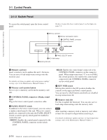
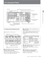
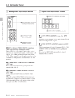
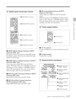
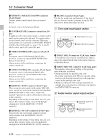
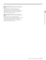
Chapter 2 Location and Function of Parts 2-2 Connector Panel 1 REMOTE 2 PARALLEL I/O(50P) connector (D-sub 50-pin) Connect remote control signals from an external device. For details, refer to the Installation Manual. 2 CONTROL PANEL connector (round type, 10pin) In addition to the lower control panel, a similar control panel can be connected to this unit. To connect such a second control panel, use this connector. When two control panels are connected, use the PANEL SELECT switch on the switch panel (see page 2-14) to specify which control panel will control this unit. 3 VIDEO CONTROL(15P) connector (D-sub 15pin) For remote control of the internal digital video processor, connect an optional BVR-50/50P Video Remote Control Unit. Always power off this unit before connecting the remote control unit. 4 VIDEO CONTROL(9P) connector (D-sub 9-pin) For remote control of the internal digital video processor, connect an optional HKDV-900 Video Remote Control Unit. Always power off this unit before connecting the remote control unit. 5 REMOTE 1-IN(9P) connector (D-sub 9-pin) When using this unit together with another HDCAM VTR, and a BVE-series BVE-700/900/910/2000/9000/ 9000P/9100/9100P or other editor, connect the optional 9-pin remote control cable from the other unit to this connector. Depending on the setting of setup menu item 211, you can use this connector alone, or in a loop-through configuration with the REMOTE 1-OUT(9P) connector. 6 REMOTE 1-OUT(9P) connector (D-sub 9-pin) This provides the loop-through output for remote control signals from the REMOTE 1-IN(9P) connector. Depending on the setting of setup menu item 211, you can use this connector alone, or in a loop-through configuration with the REMOTE 1-IN(9P) connector. 7 RS-232C connector (D-sub 9-pin) Use this for monitoring and diagnosis of the state of this unit from an external computer, using the ISR (Interactive Status Reporting) function. 7 Time code input/output section TIME CODE IN OUT 1 TIME CODE IN connector 2 TIME CODE OUT connector 1 TIME CODE IN connector (XLR 3-pin, female) To record time code from an external device, input a time code signal from the time code output connector of the other device. 2 TIME CODE OUT connector (XLR 3-pin, male) This outputs a time code according to the operating state of the unit, as follows: • During playback: the playback time code By setting setup menu item 606, you can also output the time code from the internal time code generator locked to the playback time code. • During recording: the time code generated by the internal time code generator or the time code input to the TIME CODE IN connector. 8 Audio monitor signal output section MONITOR OUTPUT R L 1 MONITOR OUTPUT R connector 2 MONITOR OUTPUT L connector 2-18 Chapter 2 Location and Function of Parts
-
 1
1 -
2
-
3
-
4
-
5
-
6
-
7
-
8
-
9
-
10
-
11
-
12
-
13
-
14
-
15
-
16
-
17
-
18
-
19
-
20
-
21
-
22
-
 23
23 -
 24
24 -
 25
25 -
 26
26 -
 27
27 -
 28
28 -
 29
29 -
 30
30 -
 31
31 -
 32
32 -
 33
33 -
34
-
35
-
36
-
37
-
38
-
39
-
40
-
41
-
42
-
43
-
44
-
45
-
46
-
47
-
48
-
49
-
50
-
51
-
52
-
53
-
54
-
55
-
56
-
57
-
58
-
59
-
60
-
61
-
62
-
63
-
64
-
65
-
66
-
67
-
68
-
69
-
70
-
71
-
72
-
73
-
74
-
75
-
76
-
77
-
78
-
79
-
80
-
81
-
82
-
83
-
84
-
85
-
86
-
87
-
88
-
89
-
90
-
91
-
92
-
93
-
94
-
95
-
96
-
97
-
98
-
99
-
100
-
101
-
102
-
103
-
104
-
105
-
106
-
107
-
108
-
109
-
110
-
111
-
112
-
113
-
114
-
115
-
116
-
117
-
118
-
119
-
120
-
121
-
122
-
123
-
124
-
125
-
126
-
127
-
128
-
129
-
130
-
131
-
132
-
133
-
134
-
135
-
136
-
137
-
138
-
139
-
140
-
141
-
142
-
143
-
144
-
145
-
146
-
147
-
148
-
149
-
150
-
151
-
152
-
153
-
154
-
155
-
156
 |
 |
