Sony HDWM2000/20 Operation Manual - Page 153
Index
 |
View all Sony HDWM2000/20 manuals
Add to My Manuals
Save this manual to your list of manuals |
Page 153 highlights
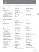
Index A AC IN connector 2-17 ALARM indicator 2-12 Analog audio input/output section 2-15 video input/output section 2-16 ASSEMBLE button 2-11 Audio control section 2-4 monitor signal output section 2-18 monitor signal selection buttons 2-5 selection function selector buttons 2-4 setting display section 2-4 AUDIO IN/OUT buttons 2-13 AUDIO INPUT (AES/EBU) connectors 2-16 AUDIO INPUT CH1 to CH4 connectors 2-15 AUDIO INPUT CH1 to CH4 LEVEL switches 2-15 AUDIO OUTPUT (AES/EBU) connectors 2-16 AUDIO OUTPUT CH1 to CH4 connectors 2-15 AUTO EDIT button 2-13 B Basic setup menu items 10-7 BLACK (function menu) 9-5 C C PHAS (function menu) 9-5 Capstan lock mode indicator 2-7 override function 4-8 CAPSTN (function menu) 9-7 Cassettes 3-8 CHANNEL CONDITION indicator 2-6 CHARA (function menu) 9-7 CH1 to CH4 buttons 2-11 CHROMA (function menu) 9-5 COMPONENT VIDEO OUTPUT connectors 2-16 COMPOSITE VIDEO OUTPUT connectors 2-16 CONFI (ON)/PREREAD indicators 2-7 CONFI (function menu) 9-3 CONFI playback 2-8 Connections to digital devices 3-1 Connector panel 2-15 Continuous editing 5-13 CONTROL PANEL connector connector panel 2-18 switch panel 2-14 Control panels 2-1 CTL/TC (function menu) 9-3 CUE button 2-11 CUE IN/OUT connectors 2-15 D DELETE button 2-12 DF (function menu) 9-4 DF indicator 2-7 Digital audio input/output section 2-16 device connection 3-1 hours meter 11-5 signal input/output section 2-17 DISPLAY FULL/FINE button 2-4 DMC EDIT button 2-12 editing 5-11 playback 4-10 Drop frame mark 3-7 mode 9-4 E EDIT button 2-10 Edit point 5-3 cue-up and preroll 5-7 modifying and deleting 5-6 setting buttons 2-13 Editing automatic editing 5-1 carrying out 5-8 continuous editing 5-13 control section 2-12 cross-fade editing 10-16 manual editing 5-14 mode setting section 2-11 preread editing 5-14 quick editing 5-13 selecting the editing mode 5-3 special methods 5-13 split editing 5-4 standalone editing 5-14 switch/menu settings 5-2 E-E mode 2-5, 2-10 EJECT button 2-2 EMPHSS (function menu) 9-6 ENTRY button 2-13 Error messages 11-2 Extended setup menu items 10-10 External device connectors 2-17 F F FWD button 2-11 Features 1-1 PHONES jack/control 2-2 F1 to F6 buttons 2-6 Format indicators 2-2 Function menu configuration 9-1 item 9-2 operation 2-6, 9-1 G Ground terminal 2-17 H HDCAM 1-1 cassettes 3-8 HDSDI INPUT connectors 2-17 HDSDI OUTPUT connectors 2-17 Head cleaning 11-1 Headphones 2-2 HOME button 2-6 HUE (function menu) 9-5 I IN/OUT buttons 2-13 INPUT button 2-4 INSERT buttons 2-11 J JOG button 2-9 indicator 2-9 Jog mode 4-7 K KEY INHI indicator 2-12 KEY INHI switch 2-14 L Level meter 2-5 Line standard indicator 2-7 LIST button 2-13 Location and function of parts connector panel 2-15 lower control panel 2-3 switch panel 2-14 upper control panel 2-2 LTC external sync 4-4 indicator 2-7 M Manual editing 5-14 MARK button 2-13 Memory card ejection button 2-14 slot 2-14 Memory stick 3-10 MEMORY indicator 2-12 MENU (function menu) 9-3 Menu control buttons 2-6 function menu 9-1 setup menus 10-1 display section 2-7 shot mark operation menu 6-2 MIXING button 2-4 Moisture condensation 11-4 MONITOR OUTPUT R/L connector 2-19 MULTI CONTROL knob 2-8 Index I-1 Index
-
 1
1 -
2
-
3
-
4
-
5
-
6
-
7
-
8
-
9
-
10
-
11
-
12
-
13
-
14
-
15
-
16
-
17
-
18
-
19
-
20
-
21
-
22
-
23
-
24
-
25
-
26
-
27
-
28
-
29
-
30
-
31
-
32
-
33
-
34
-
35
-
36
-
37
-
38
-
39
-
40
-
41
-
42
-
43
-
44
-
45
-
46
-
47
-
48
-
49
-
50
-
51
-
52
-
53
-
54
-
55
-
56
-
57
-
58
-
59
-
60
-
61
-
62
-
63
-
64
-
65
-
66
-
67
-
68
-
69
-
70
-
71
-
72
-
73
-
74
-
75
-
76
-
77
-
78
-
79
-
80
-
81
-
82
-
83
-
84
-
85
-
86
-
87
-
88
-
89
-
90
-
91
-
92
-
93
-
94
-
95
-
96
-
97
-
98
-
99
-
100
-
101
-
102
-
103
-
104
-
105
-
106
-
107
-
108
-
109
-
110
-
111
-
112
-
113
-
114
-
115
-
116
-
117
-
118
-
119
-
120
-
121
-
122
-
123
-
124
-
125
-
126
-
127
-
128
-
129
-
130
-
131
-
132
-
133
-
134
-
135
-
136
-
137
-
138
-
139
-
140
-
141
-
142
-
143
-
144
-
145
-
146
-
147
-
 148
148 -
 149
149 -
 150
150 -
 151
151 -
 152
152 -
 153
153 -
 154
154 -
 155
155 -
 156
156
 |
 |