Sony HVRM35U Product Manual (HVR-M35U Operating Manuals)
Sony HVRM35U Manual
 |
View all Sony HVRM35U manuals
Add to My Manuals
Save this manual to your list of manuals |
Sony HVRM35U manual content summary:
- Sony HVRM35U | Product Manual (HVR-M35U Operating Manuals) - Page 1
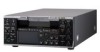
3-276-290-11 (1) Digital HD Videocassette Recorder Operating Instructions Before operating the unit, please read this manual thoroughly, and retain it for future reference. HVR-M35U/M35N/M35E/M35P © 2008 Sony Corporation - Sony HVRM35U | Product Manual (HVR-M35U Operating Manuals) - Page 2
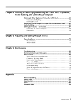
31 Inserting/Ejecting Cassettes 31 Notes on Playback/Recording 32 Recording Format and Input/Output Signals 33 Major Differences among HDV1080i, DVCAM, and DV Formats 33 Input/Output Signals in EE Mode 33 Recording Input Signals and Recording Formats 34 Playback Tape Format and Output Signals - Sony HVRM35U | Product Manual (HVR-M35U Operating Manuals) - Page 3
72 Chapter 6 Maintenance Troubleshooting 86 Warning Indicators and Messages 93 Notes on Use 95 Notes on the Videocassette Recorder 95 Cleaning of the Video Heads 95 Notes on the Video Cassettes 96 Notes on the LCD Screen 97 About Moisture Condensation 97 Digital - Sony HVRM35U | Product Manual (HVR-M35U Operating Manuals) - Page 4
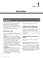
Overview 1 Chapter Features The HVR-M35U/M35N/M35E/M35P is a digital HD videocassette recorder supporting the HDV and DVCAM/DV formats. The unit produces stable, superior picture quality using digital processing and by separating image signals into color difference signals and a luminance signal - Sony HVRM35U | Product Manual (HVR-M35U Operating Manuals) - Page 5
/EBU OUT jacks, AUDIO OUT jacks, MONITOR jacks and TC OUT jack • Input-output jack: HDV/DV jack About SDI SDI is an abbreviation of Serial Digital Interface. Uncompressed HD/SD video signals are output from the HD/SD SDI OUT jack of this unit. About AES/EBU AES/EBU is a format used to - Sony HVRM35U | Product Manual (HVR-M35U Operating Manuals) - Page 6
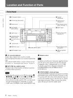
switch a q (cassette) indicator Lights when a digital video cassette is loaded. Does not light up when jack, CONTROL S jack, and HDV/DV jack. c Remote sensor Note In addition to the with the unit, the unit accepts signals from any Sony Remote Commander whose command mode is set to VTR4. - Sony HVRM35U | Product Manual (HVR-M35U Operating Manuals) - Page 7
- A portion recorded in a format set by other than [AUTO] in [HDV/DV SEL] of VTR SET" menu on page 80. OFF: Auto Repeat or timer recording is disabled. REC: Recording instructions for the "AUDIO DUB (A2) 1" button on page 11. • The setting of this switch is also effective for 4channel audio HDV - Sony HVRM35U | Product Manual (HVR-M35U Operating Manuals) - Page 8
recorded properly. Also, the time code may be recorded discontinuously. • If you change the setting of this switch while recording is in progress, the output signal via the HDV OUT jack and MONITOR VIDEO jack. ALL: Superimposes text data to HD/SD SDI OUT jack, COMPONENT OUT jacks, S VIDEO OUT jack, - Sony HVRM35U | Product Manual (HVR-M35U Operating Manuals) - Page 9
meters, etc., are displayed. (Continued) ...1) "EE" stands for "Electric to Electric." In EE mode, the video and audio signals input to the VCR's recording circuitry do not pass through any magnetic conversion circuits but are output via electric circuits only. This mode is used to check the input - Sony HVRM35U | Product Manual (HVR-M35U Operating Manuals) - Page 10
, user bits, and tape counter. The count value of the tape counter (seven digits) is displayed on a ±12-hour cycle. Note The count value of the counter [60i/50i SEL] in the [OTHERS] menu is set to [60i]. • A tape recorded using the 60i system or 24p/30p system is being used in the unit when [60i/ - Sony HVRM35U | Product Manual (HVR-M35U Operating Manuals) - Page 11
button / indicator 2 DUPLICATE button / indicator 3 REC (record) button / indicator 4 FF (fast forward) button / 61. When the unit is in the stop mode and HDV/DV signals are selected and input, you can check the HVR-M35U/M35N/M35E/ M35P time codes" on page 57. (Continued) 11 Chapter 1 - Sony HVRM35U | Product Manual (HVR-M35U Operating Manuals) - Page 12
is playing back a part of the tape where the recording format has been changed to HDV format, DVCAM format, or DV format, or between 60i system (including REW indicator lights and the PLAY indicator blinks.) For details on the [VTR SET] menu, see "VTR SET" on page 80. Notes • If you set [EE/PB SEL - Sony HVRM35U | Product Manual (HVR-M35U Operating Manuals) - Page 13
switch (page 22) -10 -2 +4 Acceptable level (max.) +18 dBu +24 dBu +30 dBu • If you input a sound at a level that exceeds the acceptable range, the recorded sound is distorted. b AUDIO REC LEVEL control knobs (CH-1 to CH-4) Use these knobs to adjust the levels of the analog audio signals input to - Sony HVRM35U | Product Manual (HVR-M35U Operating Manuals) - Page 14
indicator 2 DVCAM indicator 1 HDV indicator 8 25p indicator 9 HDV-i.LINK indicator q; DVCAM-i.LINK indicator qa DV-i.LINK indicator qs HD-SDI indicator qd SD-SDI indicator a HDV indicator Lights when the unit is in either of the following operating states. • When a tape recorded in HDV format is - Sony HVRM35U | Product Manual (HVR-M35U Operating Manuals) - Page 15
states. • When a tape recorded in 1080/25p format or 720/25p format is being played back. • When 1080/25p signals are input from the HDV/DV jack. i HDV-i.LINK indicator Lights when HDV signals are input/output through the i.LINK interface. j DVCAM-i.LINK indicator Lights when DVCAM signals are input - Sony HVRM35U | Product Manual (HVR-M35U Operating Manuals) - Page 16
HD/SD SDI OUT jack 8 RESET button 7 CONTROL S jack 6 HDV/DV 3/4 b AES/EBU OUT jacks Outputs digital audio signals in AES/EBU format. Recording: Either the time code generated by the internal time code generator or the time code input from an external device is output. For details, see "HVR-M35U - Sony HVRM35U | Product Manual (HVR-M35U Operating Manuals) - Page 17
you connect the unit and another device using the HDV/DV jack, you can minimize deterioration of picture quality during recording, dubbing, or capturing still pictures, all by means of digital signals processing. For details, refer to the instruction manual of the external device. Notes • When you - Sony HVRM35U | Product Manual (HVR-M35U Operating Manuals) - Page 18
the sync signals are distorted - Signals from a defective cassette (tape or recording condition is bad) played by an analog VCR that does not have TBC DVCAM format during signal input from the HDV/DV jack are not output. • When signals are input from the HDV/DV jack, the output signals from the HD - Sony HVRM35U | Product Manual (HVR-M35U Operating Manuals) - Page 19
Chapter 1 Overview • A LANC connection transmits command signals for playback, stop, pause playback, as well as the time code, tape counter, and data status of the unit. • Jacks labeled CONTROL L have the same function as LANC jacks. • There are some limitations when you edit an HDVformatted tape. - Sony HVRM35U | Product Manual (HVR-M35U Operating Manuals) - Page 20
in underscan mode. • Signals are output to the COMPONENT OUT jack and the HD/SD SDI OUT jack simultaneously. The setting of [SDI/CMPNT] of [VIDEO OUT VIDEO OUT jack, VIDEO OUT jack, or HDV/DV jack may be distorted for a moment. • When you play back a tape in DVCAM/DV format and while an EE picture - Sony HVRM35U | Product Manual (HVR-M35U Operating Manuals) - Page 21
75 Ω (ohms), unbalanced) Pb/Cb/B-Y, Pr/Cr/R-Y: 0.7 Vp-p (output impedance 75 Ω (ohms), unbalanced) (100% color bars with no setup) 480i/480p: Y: with 0.3 Vp-p sync negative 1080i/720p: Y/Pb/Pr: with 0.6 Vp-p 3-level sync 21 Chapter 1 Overview - Sony HVRM35U | Product Manual (HVR-M35U Operating Manuals) - Page 22
signals via the AUDIO IN jacks, use a conversion cable as shown below. (The COLD side is open.) For details on conversion cables, refer to the instruction manual of the devices you use. GND HOT COLD Note During audio dubbing, use the AUDIO IN CH-3 and CH-4 jacks. The AUDIO IN CH-1 and - Sony HVRM35U | Product Manual (HVR-M35U Operating Manuals) - Page 23
information (data codes) recorded on a tape" on page 40. n COUNTER SELECT button While the data or time counter is displayed, press this button to change the time counter display in the order of time code, user bits, and tape counter. Count value of the tape counter (seven digits) is displayed on - Sony HVRM35U | Product Manual (HVR-M35U Operating Manuals) - Page 24
back the video at the maximum speed. q INDEX MARK button Press this button during recording to mark an index. For details on indexes, see "Marking an index" on may not function properly. In this case, replace the battery with a Sony CR2025 lithium battery. Use of another battery may present a risk of - Sony HVRM35U | Product Manual (HVR-M35U Operating Manuals) - Page 25
DISPLAY button. In this operation manual, the menu screen, etc., information for normal recording or playback, such as time code VTR SET] menu, c is also displayed (page 42). d HVR-DR60/HVR-MRC1 connection indicator [HDD] is displayed while an HVR-DR60 is connected using the HDV/DV jack. When an HVR - Sony HVRM35U | Product Manual (HVR-M35U Operating Manuals) - Page 26
mode recorded on the tape with either 2CH or 4CH. When DV signals are input from the HDV/DV jack, displays the audio mode with either or . When HDV signals are input from the HDV/DV jack, displays the audio mode with either 2CH or 4CH. Note For DV format, signals other than DVCAM lock - Sony HVRM35U | Product Manual (HVR-M35U Operating Manuals) - Page 27
appears as the first digit (leftmost digit). When that value is positive, the first digit is blank. When part of the tape where the recording format has been changed among HDV, DVCAM and DV, the displayed value may again. While an HVR-DR60 or an HVR-MRC1 is connected using the HDV/DV jack, the - Sony HVRM35U | Product Manual (HVR-M35U Operating Manuals) - Page 28
as follows: In the playback mode: Detects the audio mode recorded on the tape. In the recording/EE mode: Detects the selected audio mode in [AUDIO MODE] of the [AUDIO SET] menu. When the INPUT SELECT switch is set to HDV/ DV and HDV or DV signals are being input: Detects the audio mode - Sony HVRM35U | Product Manual (HVR-M35U Operating Manuals) - Page 29
CUSTOM REPEAT screen The CUSTOM REPEAT screen is displayed when STATUS CHECK screen is set to [CUSTOM REPEAT]. The settings of [CUSTOM REPEAT] in the [VTR SET] menu are displayed. While CUSTOM REPEAT is in progress, you can also confirm the current status of CUSTOM REPEAT. 1 CUSTOM REPEAT 5/5 sc - Sony HVRM35U | Product Manual (HVR-M35U Operating Manuals) - Page 30
you use a standard DVCAM cassette, Mini-DVCAM cassette, or DigitalMaster™ shown above. thirds of the time available when HDV/DV (SP) recording is used. Cassette memory Some mini cassettes and standard cassettes have the cassette memory ( mark). The unit, however, does not support the cassette - Sony HVRM35U | Product Manual (HVR-M35U Operating Manuals) - Page 31
Chapter 2 Playback and Recording Checking the tape for slack Using a paper clip or a similar object, turn the reel gently in the direction shown by the few seconds for the unit to recognize the cassette and find the proper location on the tape being loaded. 31 Chapter 2 Playback and Recording - Sony HVRM35U | Product Manual (HVR-M35U Operating Manuals) - Page 32
record copyright control signals on the tape when it records. Limitations caused by differences in format The unit can record and play back tapes recorded in HDV format (1080/60i, 1080/24p, 1080/30p, 1080/50i and 1080/25p), DVCAM recorded in x.v.Color. • x.v.Color is a brand name that Sony is - Sony HVRM35U | Product Manual (HVR-M35U Operating Manuals) - Page 33
(NTSC only) 4) No user bits 4) 1) There are two modes for audio signal recording: Lock mode and Unlock mode. In Lock mode, the sampling frequencies of audio and signal Analog signal input Digital signal input Input jack VIDEO/S VIDEO VIDEO/ S VIDEO a HDV/DV (HDV format) HDV/DV (DVCAM or DV (SP) - Sony HVRM35U | Product Manual (HVR-M35U Operating Manuals) - Page 34
Recording Recording Format and Input/Output Signals Digital signal output section a: Output, -: No output or N/A SDI output 1) i.LINK output Digital audio output SDI DV (DVCAM/ DV) HDV AES/EBU Output signal Input signal Analog signal input Digital signal input Input jack VIDEO/S VIDEO HD - Sony HVRM35U | Product Manual (HVR-M35U Operating Manuals) - Page 35
Output, -: No output or N/A Analog video output Analog audio output Output signal VIDEO/ Format of the signals recorded on the tape S VIDEO DV DVCAM a HDV DV (SP) 1080/60i 1080/24p 1080/30p 1080/50i 1080/25p 720/30p/25p/24p a 1) a 1) 1),2) a 1),2) 1) a 1) 1) a 1) 1) a 1) 1) a 1) COMPONENT - Sony HVRM35U | Product Manual (HVR-M35U Operating Manuals) - Page 36
signal output section a: Output, -: No output or N/A SDI output i.LINK output SDI DV (DVCAM/ DV) HDV Digital audio output AES/EBU Output signal HD/SD SDI Format of the signals recorded in the tape OUT DV DVCAM a HDV DV (SP) 1080/60i 1080/24p 1080/30p 1080/50i 1080/25p 720/30p/25p/24p - Sony HVRM35U | Product Manual (HVR-M35U Operating Manuals) - Page 37
an i.LINK jack. Connect video cables and audio cables as shown below. For each jack, see page 16. Monitor/recorder HVR-M35 (rear panel) Chapter 2 Playback and Recording SDI cable (not supplied) Component video cable (not supplied) S-video cable (not supplied) Video cable (not supplied) AES/EBU - Sony HVRM35U | Product Manual (HVR-M35U Operating Manuals) - Page 38
OUT jacks and the HD/SD SDI OUT jack. Connecting the unit to a monitor equipped with an i.LINK jack The video and audio signals are sent with hardly any degradation, enabling high-quality playback to a monitor with an i.LINK connector that supports HDV, DVCAM, and DV formats. HVR-M35 (rear panel - Sony HVRM35U | Product Manual (HVR-M35U Operating Manuals) - Page 39
the unit with the i.LINK cable. For details, refer to your monitor's instruction manual. • When HDV signals are down-converted to DVCAM (or DV) format during playback of HDV recorded in 4channel audio and output to the HDV/DV jack, the output audio becomes 2-channel. You can switch the channels to - Sony HVRM35U | Product Manual (HVR-M35U Operating Manuals) - Page 40
useful functions that can be used during playback. Displaying information (data codes) recorded on a tape If you record on a tape using a Sony digital HD video camera recorder or digital camcorder, the recording information (data codes) is recorded on the tape. During playback, you can check the - Sony HVRM35U | Product Manual (HVR-M35U Operating Manuals) - Page 41
Chapter 2 Playback and Recording Playing at various speeds You can playback a tape at various speeds using the Remote Commander. HDV-formatted tape Button × toward a Sony device other than the unit, the playback speed may turn to 1/5 of normal speed. - when you play back a tape in DVCAM/DV format - Sony HVRM35U | Product Manual (HVR-M35U Operating Manuals) - Page 42
. • The unit does not support searching, reading, or writing of data on cassette memory. For duplicating with the DSR-25/45/50, see "Cassette memory" on page 30. • Searching may not be done correctly if the tapes were not recorded on Sony-brand digital video equipment. Using PB ZOOM When PB ZOOM - Sony HVRM35U | Product Manual (HVR-M35U Operating Manuals) - Page 43
. - Index signals - A portion unrecorded - A portion recorded in a format set by other than [AUTO] in [HDV/DV SEL] in the [IN/OUT REC] menu - Tape the CUSTOM REPEAT Set the following sub menus of [CUSTOM REPEAT] in the [VTR SET] menu. REPEAT TIMES ON/OFF : Selects either to enable or to disable - Sony HVRM35U | Product Manual (HVR-M35U Operating Manuals) - Page 44
position beforehand. 1 Connect the unit to an external AC timer (not supplied). HVR-M35 (rear panel) AC timer To an AC outlet 2 Set the TIMER . - Index signals - A portion unrecorded - A portion recorded in a format set by other than [AUTO] in [HDV/DV SEL] in the [IN/OUT REC] menu - Tape - Sony HVRM35U | Product Manual (HVR-M35U Operating Manuals) - Page 45
non-linear editing controller are recorded or a copy tape made from one, using digital dubbing, CUSTOM REPEAT may not be performed correctly. EDGE CROP MARKER The unit allows you to adjust the edge crop position under the following conditions: - When you output down converted HDV 16:9 wide screen - Sony HVRM35U | Product Manual (HVR-M35U Operating Manuals) - Page 46
REC] menu is set to [SQUEEZE] or [LETTER BOX] - When wide signals recorded in DVCAM or DV format are played back, or wide screen HDV/ DVCAM/DV signals are input to each VIDEO jack • While an HDV signal is input via the HDV/DV jack, and [DOWN CONVERT] of [VIDEO OUT] in the [IN/OUT REC - Sony HVRM35U | Product Manual (HVR-M35U Operating Manuals) - Page 47
are specified by the editing software. For details on the editing methods, refer to the instruction manual of the editing software. For details, see also page 67 and 68. Connections for Recording To video equipment without an i.LINK jack You can connect the unit to video equipment without - Sony HVRM35U | Product Manual (HVR-M35U Operating Manuals) - Page 48
/DV SEL] in the [IN/OUT REC] menu to [DV]. HVR-M35 (rear panel) Monitor i.LINK cable (not supplied) To digital video equipment with an i.LINK jack When you record an HDV (1080/60i, 1080/24p, 1080/ 30p, 1080/50i, 1080/25p), DVCAM, or DV format i.LINK signal, the video and audio signals are sent - Sony HVRM35U | Product Manual (HVR-M35U Operating Manuals) - Page 49
INH switch to OFF first, then stop or pause the recording. 1 Turn the power of the monitor on, then set the monitor's input according to the input signals. 2 Set up the player to play back a tape. For details, refer to the instruction manual of the player. 3 Turn the unit on. 4 When the player - Sony HVRM35U | Product Manual (HVR-M35U Operating Manuals) - Page 50
so that it does not exceed 0 dB when the audio signals are at their maximum. If the recording level exceeds 0 dB, the recorded sound will be distorted. Notes • When the unit records in DVCAM (DV) format, it supports two audio modes, with either 2-channels at FS48K or 4-channels at FS32K. It is not - Sony HVRM35U | Product Manual (HVR-M35U Operating Manuals) - Page 51
holding the REC button down. Note When the unit records HDV format images, it takes a while until recording starts. This delay, however, is not an error. scene later. When [AUTO INDEX] in the [VTR SET] menu is set to [ON], if you start recording while the tape is stopped, the unit automatically - Sony HVRM35U | Product Manual (HVR-M35U Operating Manuals) - Page 52
. 1 Connect the unit to an external AC timer (not supplied). Recording source (external tuner, etc.) HVR-M35 (rear panel) If the tape ends before the recording source stops operation The tape stops. To stop recording during timer recording Press the STOP button on the unit. To release the AC timer - Sony HVRM35U | Product Manual (HVR-M35U Operating Manuals) - Page 53
bits and time code on the unit. To copy the user bit and time code of a source tape, use [DUPLICATE PLUS] (page 80). • For a tape recorded both in HDV and DVCAM/DV formats, the time code may become garbled at a connecting portion between scenes on the tape. • If you play back an - Sony HVRM35U | Product Manual (HVR-M35U Operating Manuals) - Page 54
You can set the user bits as eight-digit hexadecimal values (base 16) to have the date, time, scene HDV signals are input from the HDV/DV jack, the user bits of HDV signals are applied. In this case, you do not have to follow the procedures below. When recording the internal color bars in HDV - Sony HVRM35U | Product Manual (HVR-M35U Operating Manuals) - Page 55
MENU] : END 5 Set the first two digits. Press the J/j buttons to select the number, then press the EXEC button. HDV/DV jack is not continuous or does not advance correctly, the value of the recorded or displayed time code may not be equal to the actual value of the input one. If you use a tape with this problem - Sony HVRM35U | Product Manual (HVR-M35U Operating Manuals) - Page 56
: Automatically sets the mode in accordance with the loaded tape. If nothing is recorded on the tape, the mode is set to the non-drop frame mode. code generated by the unit during recording is that of the non-drop frame mode. Even if 60i system signals are input to the HDV/DV jack, when [60i/50i SEL - Sony HVRM35U | Product Manual (HVR-M35U Operating Manuals) - Page 57
Chapter 3 Utilizing the Time Code HVR-M35U/M35N/M35E/M35P time codes The unit has a HDV/DV jack. The time code displayed and recorded on the tape differs as shown below when the INPUT SELECT switch is set to HDV/ DV and when it is set to other than HDV/DV. [HDV/DV IN INPUT SELECT TC] menu - Sony HVRM35U | Product Manual (HVR-M35U Operating Manuals) - Page 58
HD/SD SDI OUT jack and/or the HDV/DV jack during playback/recording or in EE mode. Time code output during playback Time codes recorded on the tape are output. Time code output during recording output from the COMPONENT OUT jack are in 720p or 1080i format, the timing of the time codes is three lines - Sony HVRM35U | Product Manual (HVR-M35U Operating Manuals) - Page 59
instruction manual. Before dubbing, you must set the format in which you want to output signals. Make [HDV/DV SEL] (page 72) and [i.LINK SET] (page 74) settings in the [IN/OUT REC] menu. For details, refer to "Major Differences among HDV1080i, DVCAM, and DV Formats" (page 33). To dub a tape recorded - Sony HVRM35U | Product Manual (HVR-M35U Operating Manuals) - Page 60
HDV signals are played back and down converted into DVCAM HDV/DV jack. Dubbing Procedures 1 Prepare the unit. Refer to "Settings for Recording" on page 49. 2 Prepare the recorder. If the recorder has an input selector switch, select an input. For details, refer to your recorder's instruction manual - Sony HVRM35U | Product Manual (HVR-M35U Operating Manuals) - Page 61
the STOP button, you can change the tape of both the player and recorder during duplication (page 63). Therefore, multiple tapes can be duplicated from multiple resource tapes, continuously. (The unit does not support the cassette memory function.) Note Use this function when making a one-to-one - Sony HVRM35U | Product Manual (HVR-M35U Operating Manuals) - Page 62
set the INPUT SELECT switch on the unit to HDV/DV. 2 Locate the points where you want to start playback and recording on each tape. 3 Press the STOP button If there is a blank portion on the tape, the first part of the recorded portion that follows may be dropped on the copied tape. • When the time - Sony HVRM35U | Product Manual (HVR-M35U Operating Manuals) - Page 63
start position or change cassette. PLAYER : [ X ] : RESTART [ x ] : END When [AUTO REW] is set to [ON], is displayed. You can eject the tape on the recorder to insert a new tape at this time. 3 Press the J button. Duplication starts again. When [AUTO REW] is set to [ON], the newly inserted tape - Sony HVRM35U | Product Manual (HVR-M35U Operating Manuals) - Page 64
/Remedy The INPUT SELECT switch on the recorder (the unit) is not set to HDV/DV. t Set the INPUT SELECT switch to HDV/DV. The i.LINK cable is not has occurred in the player. t Refer to the instruction manual of the player. There is no cassette in the recorder. The REC/SAVE switch is set to SAVE on - Sony HVRM35U | Product Manual (HVR-M35U Operating Manuals) - Page 65
Audio Dubbing You can record just the sound on a recorded tape. (Audio dubbing) Notes • You can dub the sound onto a DVCAM-formatted tape recorded in the 32 audio dubbing. Monitor Audio input Video input HD/SD SDI OUTPUT Video input COMPONENT OUTPUT HVR-M35 (rear panel) Audio output Sound - Sony HVRM35U | Product Manual (HVR-M35U Operating Manuals) - Page 66
jack cable (not supplied). 2 Set the INPUT SELECT switch to a setting other than HDV/DV. 3 Switch the INPUT LEVEL switch to select the audio input signal level (- the sound. However, there are some delays between the sound being recorded and the sound being played. When you play back the tape after - Sony HVRM35U | Product Manual (HVR-M35U Operating Manuals) - Page 67
on editing methods, refer to the instruction manual of your editing software. Connecting the Unit to a Computer HVR-M35 (rear panel) i.LINK cable the unit, which may cause a malfunction. • Before connecting the i.LINK cable, set [HDV/DV SEL] and [i.LINK SET] in the [IN/OUT REC] menu. If you perform - Sony HVRM35U | Product Manual (HVR-M35U Operating Manuals) - Page 68
on editing methods, refer to the instruction manual of your editing software. • The unit has a function to down convert HDV signals to DVCAM (DV) signals to output them from the HDV/DV jack. Some software may not edit DVCAM/DV signals that are down converted from HDV signals correctly. In this case - Sony HVRM35U | Product Manual (HVR-M35U Operating Manuals) - Page 69
[IN/OUT REC] menu to [OFF] (page 74). • To transfer picture data to a computer (editing machine) in DVCAM (DV) format, set [HDV/DV SEL] to [DV] (page 72). Then, according to the desired recording format, set [ REC MODE] to [DVCAM] or [DV SP] (page 72). Also, according to your edit software, select - Sony HVRM35U | Product Manual (HVR-M35U Operating Manuals) - Page 70
5 Chapter Adjusting and Setting Through Menus Operating Menus The unit allows you to set various parameters in the menus. Before you start using the unit, set the internal clock in [CLOCK SET] in the [OTHERS] menu. Except for clock setting, you can use all other factory-set default parameters as - Sony HVRM35U | Product Manual (HVR-M35U Operating Manuals) - Page 71
of the following menus and submenus. IN/OUT REC DISPLAY SET AUDIO SET VTR SET TC/UB SET OTHERS HDV/DV SEL (page 72) REC MODE (page 72) VIDEO OUT (page 73 (page 81) FROM REC P (page 81) TC PRESET (page 81) UB PRESET (page 81) HDV/DV IN TC (page 82) TC RUN (page 82) TC MAKE (page 82) TC FORMAT (page - Sony HVRM35U | Product Manual (HVR-M35U Operating Manuals) - Page 72
the unit is connected via an i.LINK cable to a computer supporting HDV format (see pages 48, 59). DV : Outputs signals of portions recorded in DVCAM/DV format during tape playback. When an i.LINK cable is connected, only signals in DVCAM/DV format from the HDV/DV jack are input or output for - Sony HVRM35U | Product Manual (HVR-M35U Operating Manuals) - Page 73
HD/SD SDI OUT jack and COMPONENT OUT jacks. Select from [480i], [480p/480i], [1080i HD/SD SDI OUT jack, COMPONENT OUT jacks and analog video jacks, selects the setting for converting the aspect ratio of a video recorded format input to the HDV/DV jack, the selectable back a tape in DVCAM (DV) format - Sony HVRM35U | Product Manual (HVR-M35U Operating Manuals) - Page 74
When using a duplicating function that is equipped with a device such as the DSR-25/45/ 50, select [DVCAM]. - Please note that a duplicated tape and the source tape recorded in HDV format with [DVCAM] selected do not share the same ATN (Time code value is displayed correctly). • When you change the - Sony HVRM35U | Product Manual (HVR-M35U Operating Manuals) - Page 75
/OUT REC] menu is set to [EDGE CROP]. • The edge crop marker is displayed under the following conditions: - When an HDV-formatted tape is played back - When HDV signals are input to the HDV/DV jack - When a DV-wide formatted tape is played back - When DV-wide (SD) signals are input to the - Sony HVRM35U | Product Manual (HVR-M35U Operating Manuals) - Page 76
tone signals are output from the HD/SD SDI OUT jack, HDV/DV jack, COMPONENT OUT jacks, is set to [DVCAM], color bars and tone signals will be output/recorded in DVCAM format. - When [HDV/DV SEL] is unit are generated in HDV (1080i) resolution. When a resolution other than HDV (1080i) is output, the - Sony HVRM35U | Product Manual (HVR-M35U Operating Manuals) - Page 77
is pressed Mute screen (black) Mute (no sound) a) Set the AUDIO MONITOR SELECT switch appropriately. b) When the INPUT SELECT switch is set to HDV/DV. Selects the component output level of luminance and chrominance from either BETACAM or SMPTE signals when the component output is set to 480i - Sony HVRM35U | Product Manual (HVR-M35U Operating Manuals) - Page 78
ALLSCAN MODE is for HDV format only. ALLSCAN MODE does not activate when DVCAM and DV(SP)-formatted DATE : Displays the date and time when recorded. LETTER SIZE Selects the character size of the the HVR-M35U/M35N.) D/M/Y : Displays DD/MM/YY (day/month/year). (Default setting for the HVR-M35E/ - Sony HVRM35U | Product Manual (HVR-M35U Operating Manuals) - Page 79
of the audio and video for recording. This setting is effective for digital processing and performs a clean splice during the audio editing process. JOG AUDIO (page 42) Notes • You can set this menu when recording in DV (SP) format only. • When recording in HDV or DVCAM format, the menu is set to - Sony HVRM35U | Product Manual (HVR-M35U Operating Manuals) - Page 80
Menus Chapter 5 Adjusting and Setting Through Menus VTR SET menu Icon/Menu VTR SET Submenu Setting DUPLICATE PLUS (page 61 HDV and duplicates. DVCAM : Duplicates DVCAM format only. DV SP : Duplicates DV (SP) format only. AUTO REW BON : Rewinds the tape on both the player and the recorder - Sony HVRM35U | Product Manual (HVR-M35U Operating Manuals) - Page 81
Menu VTR SET . STEP FORWARD : Forwards one frame. Note If you play a tape recorded in HDV format with [STEP FORWARD] selected, the tape advances a few frames forward : Sets the user bits value. (You can set the user bits as eight-digit hexadecimal values (0 to 9, A to F) (base 16) to have the date - Sony HVRM35U | Product Manual (HVR-M35U Operating Manuals) - Page 82
and Setting Through Menus Icon/Menu Submenu Setting TC/UB SET HDV/DV IN TC Selects whether to record internal time code or external time code while the unit records (page 53) signals input from the HDV/DV jack. BINTERNAL : Records the time code generated by the internal time code generator - Sony HVRM35U | Product Manual (HVR-M35U Operating Manuals) - Page 83
INDEX MARK a) AUDIO DUB (A2) button AUDIO DUB a) HDV t DV CONV c) SDI/CMPNT c) RESET (A3) botton portion recorded on a tape is played back and stopped. Use END SEARCH to check the last picture recorded. Once • The unit accepts signals from any Sony Remote Commander with its command mode set to - Sony HVRM35U | Product Manual (HVR-M35U Operating Manuals) - Page 84
also available with pictures output from the HDV/DV jack. Use caution when dubbing and editing a picture via the HDV/DV jack. Sets beeps and/or 98). HOURS METER (page 98) Displays the accumulated time counts (using the digital hours meter) in units of 10 hours or 10 counts. OPERATION :Power - Sony HVRM35U | Product Manual (HVR-M35U Operating Manuals) - Page 85
Chapter 5 Adjusting and Setting Through Menus Icon/Menu OTHERS Submenu 60i/50i SEL (page 49) Setting Switches between 1080/60i (NTSC) and 1080/50i (PAL). 1 Press the J/j buttons to select [YES], then press the EXEC button. 60i/50i SEL Change to 50i? Reboots after change. YES NO VCR PROFILE - Sony HVRM35U | Product Manual (HVR-M35U Operating Manuals) - Page 86
Troubleshooting Please check the following before contacting your Sony dealer. General Operation Troubles and [START TIME] of [CUSTOM REPEAT] in the [VTR SET] menu is set to [ON], the unit starts unit are correct, you cannot make the unit record using the DSRM-10 Remote Control Unit (not supplied - Sony HVRM35U | Product Manual (HVR-M35U Operating Manuals) - Page 87
Symptom Whenever you connect the unit to an AC outlet, the unit turns on automatically. No picture on the LCD monitor. When you select an item in [VCR PROFILE] of the [OTHERS] menu, "---ERROR!---" is displayed on the right of the profile list. Also, the item which "---ERROR!---" is displayed cannot - Sony HVRM35U | Product Manual (HVR-M35U Operating Manuals) - Page 88
Troubleshooting memory data and title are not • The unit does not support the cassette memory function and therefore such data displayed when using a tape recorded in LP mode of the DV format. t The unit can play back only tapes recorded in the HDV, DVCAM or DV (SP) formats. A tape recorded in LP - Sony HVRM35U | Product Manual (HVR-M35U Operating Manuals) - Page 89
flattened. t When you output from the HD/SD SDI OUT jack and COMPONENT OUT jacks HDV/DV IN TC] in the [TC/ UB SET] menu is set to [EXTERNAL], the time code of the input i.LINK signal is not recorded. • The i.LINK signal output from the digital Set [FROM STILL] in the [VTR SET] menu to [STOP]. If - Sony HVRM35U | Product Manual (HVR-M35U Operating Manuals) - Page 90
not function as part of a digital non-linear editing system. • The INPUT SELECT switch is set to a setting other than HDV/DV. t Set it to HDV/DV. • The editing controller or the editing software is not compatible with the unit. t Refer to the instruction manuals of the controller or the software - Sony HVRM35U | Product Manual (HVR-M35U Operating Manuals) - Page 91
[DOWN CONVERT] [SDI/CMPNT] [HDV t DV CONV] [DOWN CONVERT] Setting HDV (HDV1080i) SQUEEZE or LETTER BOX 480p/480i, 576p/576i DVCAM or DV SP Set to EDGE MODE] in [DISPLAY SET] Setting HDV (1080i or 720p) 480i, 576i, 480p/480i, 576p/576i ON Recording/Dubbing Symptom Whenever you connect the unit - Sony HVRM35U | Product Manual (HVR-M35U Operating Manuals) - Page 92
digital non-linear editing system. The functions on the unit do not operate. Cause/Remedy Confirm the level of the sound output from the player by referring to the player's instruction manual onto an HDV or DV-formatted tape. t Sounds can be dubbed only onto a DVCAM-formatted tape (recorded) in the - Sony HVRM35U | Product Manual (HVR-M35U Operating Manuals) - Page 93
:ss (Self-diagnosis display) Cause/Corrective Action If an error still recurs after you retry the corrective action several times, contact Sony Customer Service or your place of purchase. C:21:ss t Condensation has occurred. Remove the cassette and insert it again after approximately 1 hour (page - Sony HVRM35U | Product Manual (HVR-M35U Operating Manuals) - Page 94
add audio. INPUT SELECT is set to HDV/DV. Not recorded in DVCAM mode. Cannot add audio. Cannot add audio. Cannot add audio on the blank portion of a tape. HDV recorded tape. Cannot add audio. Cannot add audio. "HDV/DV SEL" is set to HDV. Cannot record due to copyright protection. Change to correct - Sony HVRM35U | Product Manual (HVR-M35U Operating Manuals) - Page 95
to radiation A malfunction may occur. Checking the video heads every 1000 hours A VCR is a high-precision piece of equipment that records and plays back the picture recorded on a magnetic tape. In particular, the video heads and other mechanical parts may become dirty or worn. To maintain a clean - Sony HVRM35U | Product Manual (HVR-M35U Operating Manuals) - Page 96
recording. Image when the video head is dirty With an HDV After with new ones. Please consult your Sony dealer. Notes on the Video Cassettes disappears With a DV/DVCAM A moldy tape A problem with the tape. Avoid using that tape. For details, refer to your cleaning cassette's instruction manual - Sony HVRM35U | Product Manual (HVR-M35U Operating Manuals) - Page 97
tiny black points and/or bright points (red, blue, green or white) that constantly appear on the LCD screen. These points do not affect the recorded picture in any way. Do not place the unit with the LCD screen pointing toward the sun. Otherwise, the unit may be damaged. To clean - Sony HVRM35U | Product Manual (HVR-M35U Operating Manuals) - Page 98
scheduling maintenance. In general, consult your Sony dealer about necessary periodic maintenance checks. The digital hours meter has the following four display and then start using the unit. If you do not need to record the date and time when the rechargeable battery is not fully charged, you - Sony HVRM35U | Product Manual (HVR-M35U Operating Manuals) - Page 99
case, select [LOCK MODE] if required. Recording tapes used when the unit serves as a recorder Input signal format NTSC or PAL -: Setting independent Menu item REC MODE DVCAM DV SP AUDIO LOCK - LOCK MODE UNLOCK MODE Recording tape format (AUDIO MODE) DVCAM (LOCK MODE) DV (LOCK MODE) DV (UNLOCK - Sony HVRM35U | Product Manual (HVR-M35U Operating Manuals) - Page 100
back a tape employing a copy-protection signal on the unit, you cannot record images from the unit to other equipment. • You cannot up convert DVCAM(DV) format to HDV format on the unit. • During playback in HDV, if [DV SP] is selected from [HDV t DV CONV] in [i.LINK SET], AUDIO MODE is fixed to - Sony HVRM35U | Product Manual (HVR-M35U Operating Manuals) - Page 101
unit is used as a recorder i.LINK input format HDV DVCAM DV Menu item HDV/DV SEL AUTO HDV DV AUTO HDV DV AUTO HDV DV REC MODE 1) - - - DVCAM DV SP - DVCAM DV SP DVCAM DV SP - DVCAM DV SP Recording tape format (AUDIO MODE) 3) HDV (LOCK MODE) HDV (LOCK MODE) No recording DVCAM (Complies with input - Sony HVRM35U | Product Manual (HVR-M35U Operating Manuals) - Page 102
operate with some i.LINK video equipment such as digital televisions, DVD recorders/players, and MICROMV recorders/players even if they are equipped with an i.LINK jack. Before connecting to another equipment, confirm whether this equipment is HDV/DVCAM (DV) compatible. For details on precautions on - Sony HVRM35U | Product Manual (HVR-M35U Operating Manuals) - Page 103
CCIR standard system Usable cassettes Standard DVCAM cassettes with the mark Mini DVCAM cassettes with the mark Tape speed (HDV) Approx. 18.812 mm/s Tape speed (DVCAM) Approx. 28.218 mm/s Tape speed (DV) SP: Approx. 18.812 mm/s Recording/playback time (HDV) Approx. 276 min (using PHDV-276DM - Sony HVRM35U | Product Manual (HVR-M35U Operating Manuals) - Page 104
negative 1080i/720p: Y/Pb/Pr: with 0.6 Vp-p 3-level sync HDV/DV jack i.LINK (IEEE 1394, 6-pin connector S100) HD/SD HVR-M35U AC100 V-120 V, 60 Hz HVR-M35N AC100 V-240 V, 50/60 Hz HVR-M35E AC100 V-240 V, 50 Hz HVR-M35P AC100 V-240 V, 50/60 Hz Power consumption (during playback) HVR-M35U 15 W HVR - Sony HVRM35U | Product Manual (HVR-M35U Operating Manuals) - Page 105
(11/32) Appendix 212 (8 3/8) 175 (7) Unit: mm (inches) Mass Approx. 4.4 kg (9 lb. 12 oz.) Supplied accessories Remote Commander (1) Power cord (1) Cleaning cassette (1) Operating Instructions (1) Design and specifications are subject to change without notice. 10 (13/32) 88 (3 1/2) Appendix 105 - Sony HVRM35U | Product Manual (HVR-M35U Operating Manuals) - Page 106
96 Troubleshooting 87 Digital hours meter 98 For submenu items, see "Submenu Index" on page 108. Digital DVCAM cassette 30 DVCAM HD/SD SDI OUT jack 18 HDV cassette 30 HDV format 4, 33 HDV/DV jack 17 Dubbing 59 Editing 67 Playback 38 Recording 48 I i.LINK 102 t HDV SET 81 VTR SET - Sony HVRM35U | Product Manual (HVR-M35U Operating Manuals) - Page 107
86 U Unlock mode 33 Usable cassette 30 User bits 53 V VIDEO jack 20 VTR SET menu 80 R Rear panel 16 REC button 12 Rechargeable battery 98 Recording 47 Troubleshooting 91 Recording format 33 during recording 34 Remaining tape time 26 Remote Commander 23 REPEAT CYCLE 43 REPEAT TIMES - Sony HVRM35U | Product Manual (HVR-M35U Operating Manuals) - Page 108
D DATA CODE 78 DATE DISPLAY 78 DUPLICATE PLUS 80 E EE/PB SEL 77 F FF/REW SPEED 80 FROM REC P 81 FROM STILL 81 H HDV/DV IN TC 82 HDV/DV SEL 72 HOURS METER 84 L LANGUAGE 83 LCD BLACK 78 LCD BRIGHT 78 LCD COLOR 78 LETTER SIZE 78 M MARKER BURN 78 - Sony HVRM35U | Product Manual (HVR-M35U Operating Manuals) - Page 109
- Sony HVRM35U | Product Manual (HVR-M35U Operating Manuals) - Page 110
- Sony HVRM35U | Product Manual (HVR-M35U Operating Manuals) - Page 111
- Sony HVRM35U | Product Manual (HVR-M35U Operating Manuals) - Page 112
Printed on 70% or more recycled paper using VOC (Volatile Organic Compound)-free GB vegetable oil based ink. Printed in Japan
-
 1
1 -
 2
2 -
 3
3 -
 4
4 -
 5
5 -
 6
6 -
 7
7 -
8
-
9
-
10
-
11
-
12
-
13
-
14
-
15
-
16
-
17
-
18
-
19
-
20
-
21
-
22
-
23
-
24
-
25
-
26
-
27
-
28
-
29
-
30
-
31
-
32
-
33
-
34
-
35
-
36
-
37
-
38
-
39
-
40
-
41
-
42
-
43
-
44
-
45
-
46
-
47
-
48
-
49
-
50
-
51
-
52
-
53
-
54
-
55
-
56
-
57
-
58
-
59
-
60
-
61
-
62
-
63
-
64
-
65
-
66
-
67
-
68
-
69
-
70
-
71
-
72
-
73
-
74
-
75
-
76
-
77
-
78
-
79
-
80
-
81
-
82
-
83
-
84
-
85
-
86
-
87
-
88
-
89
-
90
-
91
-
92
-
93
-
94
-
95
-
96
-
97
-
98
-
99
-
100
-
101
-
102
-
103
-
104
-
105
-
106
-
107
-
108
-
109
-
110
-
111
-
112
 |
 |
3-276-290-
11
(1)
Digital HD
Videocassette
Recorder
Operating Instructions
Before operating the unit, please read this manual thoroughly,
and retain it for future reference.
HVR-M35U/M35N/M35E/M35P
© 2008 Sony Corporation