Sony HVRM35U Product Manual (HVR-M35U Operating Manuals) - Page 17
POWER main power switch, HDV/DV jack 6-pin, CONTROL S jack, CMPNT] of [VIDEO OUT] in the [IN/OUT REC]
 |
View all Sony HVRM35U manuals
Add to My Manuals
Save this manual to your list of manuals |
Page 17 highlights
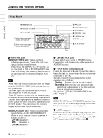
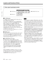
Chapter 1 Overview e POWER (main power) switch The main power switch of the unit. When this switch is in the "|" position, the ON/STANDBY lamp on the front panel lights up in green. (In the standby mode, the ON/ STANDBY lamp lights up in red.) When you do not intend to use the unit for a long time, press the "a" (OFF) marked side of the POWER switch. f HDV/DV jack (6-pin) Use this jack to input/output digital signals that comply with the i.LINK standard. Use this jack when a device connected to the unit has an i.LINK jack. If you connect the unit and another device using the HDV/DV jack, you can minimize deterioration of picture quality during recording, dubbing, or capturing still pictures, all by means of digital signals processing. For details, refer to the instruction manual of the external device. Notes • When you connect a computer and the unit with an i.LINK cable, check the direction of the jack. If you forcibly insert the jack, the terminal may be damaged or cause the unit to malfunction. • This jack is only compatible with HDV (1080i)/ DVCAM/DV signals. For details, see "About i.LINK" on page 102. • If video signals have been input to the HDV/DV jack and you output these video signals to the S VIDEO OUT or VIDEO OUT jacks, the sync and burst of the corresponding EE picture is not synchronized. • If the unit is connected to a device equipped with an i.LINK jack, when you intend to disconnect or reconnect the i.LINK cable, turn off the device and pull out the plug of its power cord from the AC outlet beforehand. If you connect or disconnect the i.LINK cable while the device is connected to the AC outlet, high-voltage current (8 to 40 V) is output from the i.LINK jack of the device to the unit. This may cause a malfunction. • Even though the HDV/DV jack of the unit is a 6-pin type, no power is supplied. For details on each setting when HDV/DV signals are input, see "HDV/DV SEL" (page 72). • A video signal which is input from the HDV/DV jack will be output directly to the HD/SD SDI OUT jack, the COMPONENT OUT jacks, the S VIDEO OUT jack, and the VIDEO OUT jack with the jitter of the i.LINK signal. This jitter may be displayed on the connected monitor. Be aware of this jitter when you connect other recording device to these jacks. This jitter will not appear on a recording with the unit. • When SD-quality signals are input via the HDV/DV jack, no signal is output from the HD/SD SDI OUT jack. However, input HD-quality signals are output from the HD/SD SDI OUT jack. • When you change the video format setting of [SDI/ CMPNT] in [VIDEO OUT] of the [IN/OUT REC] menu, the video signal output from the S VIDEO OUT jack, the VIDEO OUT jack, or the HDV/DV jack may be distorted. For details on the output of the HDV/DV jack, see "Notes on all video output jacks" (page 17). g CONTROL S jack Connect this jack to a DSRM-10 remote control unit (not supplied) to operate the unit. You can also use a DSRM-20 (no longer manufactured: not supplied). Note When you use a CONTROL S device, set [COMMANDER] in the [OTHERS] menu to [CONTROL S]. Notes on all video output jacks • When you change the video format setting of [SDI/ CMPNT] and [DOWN CONVERT] of [VIDEO OUT] in the [IN/OUT REC] menu, [ALLSCAN MODE] in the [DISPLAY SET] menu, or [HDV t DV CONV] and [DOWN CONVERT] of [i.LINK SET] in the [IN/ OUT REC] menu, the image may be distorted for a moment. Also, the above settings may cause restrictions on the video output of the unit. For details, refer to the table on page 91 and the instructions for each menu setting. • When you change the video format setting of [SDI/ CMPNT] of [VIDEO OUT] in the [IN/OUT REC] menu, the video signals output from S VIDEO OUT jack, VIDEO OUT jack, or HDV/DV jack may be distorted. (Continued) 17 Chapter 1 Overview
-
 1
1 -
2
-
3
-
4
-
5
-
6
-
7
-
8
-
9
-
10
-
11
-
 12
12 -
 13
13 -
 14
14 -
 15
15 -
 16
16 -
 17
17 -
 18
18 -
 19
19 -
 20
20 -
 21
21 -
 22
22 -
23
-
24
-
25
-
26
-
27
-
28
-
29
-
30
-
31
-
32
-
33
-
34
-
35
-
36
-
37
-
38
-
39
-
40
-
41
-
42
-
43
-
44
-
45
-
46
-
47
-
48
-
49
-
50
-
51
-
52
-
53
-
54
-
55
-
56
-
57
-
58
-
59
-
60
-
61
-
62
-
63
-
64
-
65
-
66
-
67
-
68
-
69
-
70
-
71
-
72
-
73
-
74
-
75
-
76
-
77
-
78
-
79
-
80
-
81
-
82
-
83
-
84
-
85
-
86
-
87
-
88
-
89
-
90
-
91
-
92
-
93
-
94
-
95
-
96
-
97
-
98
-
99
-
100
-
101
-
102
-
103
-
104
-
105
-
106
-
107
-
108
-
109
-
110
-
111
-
112
 |
 |
