Sony HVRM35U Product Manual (HVR-M35U Operating Manuals) - Page 13
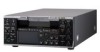
Audio control AUDIO INPUT AUTO/MANU/FIX switch, AUDIO REC LEVEL control knobs, CH-1 to CH-4
 |
View all Sony HVRM35U manuals
Add to My Manuals
Save this manual to your list of manuals |
Page 13 highlights
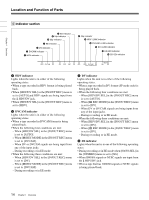
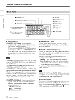
Chapter 1 Overview 3 Audio control section EJECT button (see qd in page 8) 1 AUDIO INPUT (AUTO/MANU/FIX) switch 1Monitor display section (see page 9) 2 AUDIO REC LEVEL control knob a AUDIO INPUT (AUTO/MANU/FIX) switch Switches the audio recording level adjustment mode. AUTO : Adjusts AUDIO REC LEVEL automatically. (Adjustment of AUDIO REC LEVEL control knobs 2 is disabled.) For acceptable recording levels, see the table below. INPUT LEVEL switch (page 22) -10 -2 +4 Acceptable level (max.) +18 dBu +24 dBu +30 dBu MANU : Enables the AUDIO REC LEVEL control knobs 2. FIX : Fixes AUDIO REC LEVEL at the intermediate value. (Adjustment using the AUDIO REC LEVEL control knobs 2 is disabled.) For acceptable recording levels, see the table below. INPUT LEVEL switch (page 22) -10 -2 +4 Acceptable level (max.) +18 dBu +24 dBu +30 dBu • If you input a sound at a level that exceeds the acceptable range, the recorded sound is distorted. b AUDIO REC LEVEL control knobs (CH-1 to CH-4) Use these knobs to adjust the levels of the analog audio signals input to the unit for each channel. These knobs are enabled only when the AUDIO INPUT (AUTO/MANU/FIX) switch 1 is set to MANU. To display the audio level meters on the LCD monitor, press the STATUS CHECK button. For details on the audio level meter, see "STATUS CHECK screen" on page 27. Note You cannot adjust the audio level using these knobs while i.LINK signals are input. Notes • When i.LINK signals are input to the unit, the sound recorded retains the signal input level, regardless of the setting of this switch. • Even when this switch is set to AUTO, the setting is not effective against a volume level which exceeds the dynamic range of the input amplifier. 13 Chapter 1 Overview
-
 1
1 -
2
-
3
-
4
-
5
-
6
-
7
-
 8
8 -
 9
9 -
 10
10 -
 11
11 -
 12
12 -
 13
13 -
 14
14 -
 15
15 -
 16
16 -
 17
17 -
 18
18 -
19
-
20
-
21
-
22
-
23
-
24
-
25
-
26
-
27
-
28
-
29
-
30
-
31
-
32
-
33
-
34
-
35
-
36
-
37
-
38
-
39
-
40
-
41
-
42
-
43
-
44
-
45
-
46
-
47
-
48
-
49
-
50
-
51
-
52
-
53
-
54
-
55
-
56
-
57
-
58
-
59
-
60
-
61
-
62
-
63
-
64
-
65
-
66
-
67
-
68
-
69
-
70
-
71
-
72
-
73
-
74
-
75
-
76
-
77
-
78
-
79
-
80
-
81
-
82
-
83
-
84
-
85
-
86
-
87
-
88
-
89
-
90
-
91
-
92
-
93
-
94
-
95
-
96
-
97
-
98
-
99
-
100
-
101
-
102
-
103
-
104
-
105
-
106
-
107
-
108
-
109
-
110
-
111
-
112
 |
 |