Sony HVRM35U Product Manual (HVR-M35U Operating Manuals) - Page 26
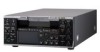
INPUT SELECT indicator, Index indicator
 |
View all Sony HVRM35U manuals
Add to My Manuals
Save this manual to your list of manuals |
Page 26 highlights
Chapter 1 Overview Displaying Various Data i Time counter (time code/user bits/count value of the counter) indicator Displays the count value of the counter, time code, or user bits. By pressing the COUNTER SELECT button on the front panel, you can select the item to be displayed. When the time code is displayed, TC appears to its left. In the drop frame mode, a period is displayed between the minutes and seconds (i.e., 00:12.58:00). When the user bits are displayed, UB appears to their left. When the count value of the counter is negative, "-" appears as the first digit (leftmost digit). When that value is positive, the first digit is blank. The count value of the counter consists of seven digits. If the self-diagnostic function is enabled, diagnostics code numbers are displayed. Note When you playback a tape without a time code or with a time code recorded in different formats, the time code cannot be displayed correctly. j Remaining tape time indicator Displays the remaining tape time. For details, see " REMAINING" in the "DISPLAY SET" menu on page 78. Note When you insert a cassette of which the tape has been rewound to the beginning, this indicator does not show the remaining tape time. The remaining tape time is displayed after the tape runs for a while. k INPUT SELECT indicator Changes according to the position of the INPUT SELECT switch. ([HDV/DV IN], [S VIDEO IN] or [VIDEO IN]) l (Index) indicator Displays when an index has been marked. m Search indicator Displays the search mode when you search for scenes using the Remote Commander. For details on the search function, see "Searching using the search function" on page 42. n Black signal indicator Displays a Black signal indicator when [COLOR BAR] is set to [ON] and [TYPE] is set to [BLACK] in [COLOR BAR] of the [IN/OUT REC] menu. For details on color bar type, see "COLOR BAR" in the "IN/ OUT REC" menu on page 76. o Audio mode indicator During recording in DV mode, displays when you select [FS32K] for [AUDIO MODE] in the [AUDIO SET] menu. When you select [FS48K], is displayed. During recording in HDV mode, displays the audio mode with either 2CH or 4CH. During DV format playback or audio dubbing, displays the audio mode recorded on the tape with either or . During HDV format playback, displays the audio mode recorded on the tape with either 2CH or 4CH. When DV signals are input from the HDV/DV jack, displays the audio mode with either or . When HDV signals are input from the HDV/DV jack, displays the audio mode with either 2CH or 4CH. Note For DV format, signals other than DVCAM lock mode will become non-standard audio and / will be displayed during playback or when the signal is input from the HDV/DV jack. p Date/time indicator When you press the DATA CODE button of the Remote Commander or set [DATA CODE] in the [DISPLAY SET] menu to [DATE], you can display the recording date/time. For details on the date/time indicator, see "Displaying information (data codes) recorded on a tape" on page 40. Time counter screen To display the time counter on the LCD monitor, press the DISPLAY button. On the time counter screen, the time data (count value of the counter/time code/user bits) is displayed. While the time counter is displayed, the position of the time counter can be moved up and down by pressing the J/j buttons. When the small size time counter is displayed, the position of the time counter can be moved not only up and down, but also to the left and right by pressing the K/k buttons. 26 Chapter 1 Overview
-
 1
1 -
2
-
3
-
4
-
5
-
6
-
7
-
8
-
9
-
10
-
11
-
12
-
13
-
14
-
15
-
16
-
17
-
18
-
19
-
20
-
 21
21 -
 22
22 -
 23
23 -
 24
24 -
 25
25 -
 26
26 -
 27
27 -
 28
28 -
 29
29 -
 30
30 -
 31
31 -
32
-
33
-
34
-
35
-
36
-
37
-
38
-
39
-
40
-
41
-
42
-
43
-
44
-
45
-
46
-
47
-
48
-
49
-
50
-
51
-
52
-
53
-
54
-
55
-
56
-
57
-
58
-
59
-
60
-
61
-
62
-
63
-
64
-
65
-
66
-
67
-
68
-
69
-
70
-
71
-
72
-
73
-
74
-
75
-
76
-
77
-
78
-
79
-
80
-
81
-
82
-
83
-
84
-
85
-
86
-
87
-
88
-
89
-
90
-
91
-
92
-
93
-
94
-
95
-
96
-
97
-
98
-
99
-
100
-
101
-
102
-
103
-
104
-
105
-
106
-
107
-
108
-
109
-
110
-
111
-
112
 |
 |
