Sony HVRM35U Product Manual (HVR-M35U Operating Manuals) - Page 8
INDEX A1 button, INPUT SELECT switch, HDV/DV, S VIDEO, Speaker bottom panel, DISPLAY OUTPUT switch
 |
View all Sony HVRM35U manuals
Add to My Manuals
Save this manual to your list of manuals |
Page 8 highlights
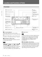
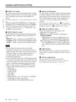
Chapter 1 Overview Location and Function of Parts i INDEX (A1) button Press this button to write an index mark while recording. Indexing is useful when you search for scenes on a tape. Also, this button can be used as the ASSIGN (A1) button. For details on Indexing, see "Recording Functions" on page 51. When you change the ASSIGN button's setting with [ASSIGN [A1]] of [ASSIGN BTN] in the [OTHERS] menu, this button executes the function you have set. For details on ASSIGN buttons, see "ASSIGN BTN" in the "OTHERS" menu on page 83. j INPUT SELECT switch Use this button to select the signal input jack from the HDV/DV jack, S VIDEO IN jack, and VIDEO IN jack. HDV/DV: Inputs a signal from the HDV/DV jack. S VIDEO: Inputs a signal from the S VIDEO IN jack. VIDEO: Inputs a signal from the VIDEO IN jack. Notes • Do not change the setting of this switch while recording is in progress, or it will cause noise to be added to images and sounds. Also, the part of the tape where the change of setting is applied will not be recorded properly. Also, the time code may be recorded discontinuously. • If you change the setting of this switch while recording is in progress, the output signal via the HDV/DV jack may be interrupted. Also, the unit may detect signals, such as a copyright information signal, incorrectly. • When a signal is input via the HDV/DV jack, the settings of the menus listed below are unavailable. - 60i/50i SEL - AUDIO MODE - AUDIO LOCK - AGC CH1,2 - AGC CH3,4 - INPUT LEVEL (-10/-2/+4) switch in AUDIO IN - AUDIO REC LEVEL control knob - AUDIO INPUT (AUTO/MANU/FIX) switch k Speaker (bottom panel) Use this speaker to monitor sounds in monaural during recording or playback. The volume control level and audio signals to be monitored are set to be the same as that of the headphones output. When headphones are connected, no sound is produced from the built-in speaker. For details on the volume control, see "7 5/ i (speaker/ phones) LEVEL control knob" on page 7. For details on the headphones output, see "8 i (phones) jack" on page 7. l DISPLAY OUTPUT switch Selects the destination for the text data to be superimposed via output jacks. OFF: Does not output text data to superimpose. S VIDEO/VIDEO: Superimposes text data to S VIDEO OUT jack, VIDEO OUT jack and MONITOR VIDEO jack. ALL: Superimposes text data to HD/SD SDI OUT jack, COMPONENT OUT jacks, S VIDEO OUT jack, VIDEO OUT jack and MONITOR VIDEO jack. m EJECT button Press this button to eject a cassette. If you press this button while a cassette is inside the unit, the cassette is ejected. n Cassette compartment Insert a standard-size or mini-size cassette. For details on cassettes that can be used, see "Notes on Power Supply and Video Cassettes" on page 30. 8 Chapter 1 Overview
-
 1
1 -
2
-
 3
3 -
 4
4 -
 5
5 -
 6
6 -
 7
7 -
 8
8 -
 9
9 -
 10
10 -
 11
11 -
 12
12 -
 13
13 -
14
-
15
-
16
-
17
-
18
-
19
-
20
-
21
-
22
-
23
-
24
-
25
-
26
-
27
-
28
-
29
-
30
-
31
-
32
-
33
-
34
-
35
-
36
-
37
-
38
-
39
-
40
-
41
-
42
-
43
-
44
-
45
-
46
-
47
-
48
-
49
-
50
-
51
-
52
-
53
-
54
-
55
-
56
-
57
-
58
-
59
-
60
-
61
-
62
-
63
-
64
-
65
-
66
-
67
-
68
-
69
-
70
-
71
-
72
-
73
-
74
-
75
-
76
-
77
-
78
-
79
-
80
-
81
-
82
-
83
-
84
-
85
-
86
-
87
-
88
-
89
-
90
-
91
-
92
-
93
-
94
-
95
-
96
-
97
-
98
-
99
-
100
-
101
-
102
-
103
-
104
-
105
-
106
-
107
-
108
-
109
-
110
-
111
-
112
 |
 |
