Sony HVRM35U Product Manual (HVR-M35U Operating Manuals) - Page 22
INPUT LEVEL -10/-2/+4 switch, AUDIO IN CH-1 to CH-4 jacks, Audio signal input/output
 |
View all Sony HVRM35U manuals
Add to My Manuals
Save this manual to your list of manuals |
Page 22 highlights
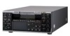
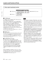
Chapter 1 Overview Location and Function of Parts 2 Audio signal input/output section 1 INPUT LEVEL switch 2 AUDIO IN jacks 3 AUDIO OUT jacks a INPUT LEVEL (-10/-2/+4) switch Select one from -10 dB, -2 dB, or +4 dB, according to the audio level of the signal input via the AUDIO IN jacks. Note If this switch setting is not appropriate, clipping distortion or noise may occur. For more information on the setting of this switch, see "When you set the INPUT LEVEL switch:" on page 92. b AUDIO IN CH-1 to CH-4 jacks Used to input analog audio signals (CH-1 to CH-4). During audio dubbing, sounds are dubbed onto channels 3 and 4. c AUDIO OUT CH-1 to CH-4 jacks Used to output audio signals (CH-1 to CH-4). Note To input balanced audio signals via the AUDIO IN jacks, use a conversion cable as shown below. (The COLD side is open.) For details on conversion cables, refer to the instruction manual of the devices you use. GND HOT COLD Note During audio dubbing, use the AUDIO IN CH-3 and CH-4 jacks. The AUDIO IN CH-1 and CH-2 jacks cannot be used for audio dubbing. 22 Chapter 1 Overview
-
 1
1 -
2
-
3
-
4
-
5
-
6
-
7
-
8
-
9
-
10
-
11
-
12
-
13
-
14
-
15
-
16
-
 17
17 -
 18
18 -
 19
19 -
 20
20 -
 21
21 -
 22
22 -
 23
23 -
 24
24 -
 25
25 -
 26
26 -
 27
27 -
28
-
29
-
30
-
31
-
32
-
33
-
34
-
35
-
36
-
37
-
38
-
39
-
40
-
41
-
42
-
43
-
44
-
45
-
46
-
47
-
48
-
49
-
50
-
51
-
52
-
53
-
54
-
55
-
56
-
57
-
58
-
59
-
60
-
61
-
62
-
63
-
64
-
65
-
66
-
67
-
68
-
69
-
70
-
71
-
72
-
73
-
74
-
75
-
76
-
77
-
78
-
79
-
80
-
81
-
82
-
83
-
84
-
85
-
86
-
87
-
88
-
89
-
90
-
91
-
92
-
93
-
94
-
95
-
96
-
97
-
98
-
99
-
100
-
101
-
102
-
103
-
104
-
105
-
106
-
107
-
108
-
109
-
110
-
111
-
112
 |
 |
