TP-Link TL-MR3420 User Guide - Page 11
The Rear Panel, TL-MR3420, Status, Indication, Wireless antenna, POWER - 3g router
 |
UPC - 845973051495
View all TP-Link TL-MR3420 manuals
Add to My Manuals
Save this manual to your list of manuals |
Page 11 highlights
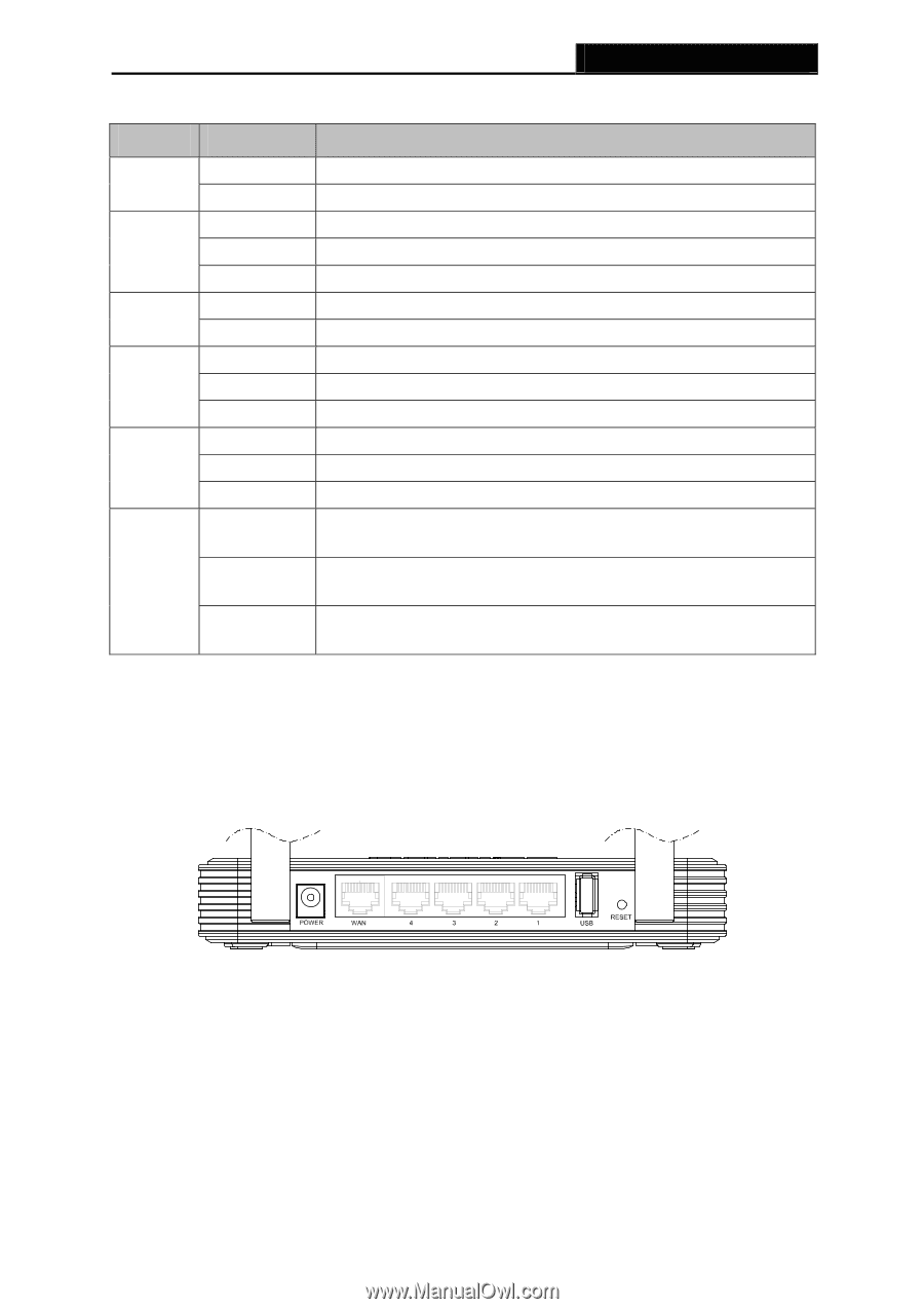
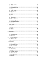
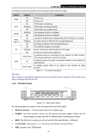
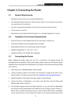
TL-MR3420 3G/3.75G Wireless N Router The Router's LEDs are located on the front panel (View from left to right). Name Status Indication PWR On Power is on. Off Power is off. On The Router is initializing. SYS Flashing The Router is working properly. Off The Router has a system error. WLAN Flashing Off The Wireless function is enabled. The Wireless function is disabled. WAN, LAN1-4 On Flashing Off A device is linked to the corresponding port but there is no activity. An active device is linked to the corresponding port. No device is linked to the corresponding port. On The USB 3G dongle is connected. 3G Flashing Data is received or sent through the 3G dongle. Off No device is linked to the USB port. Slow Flash A wireless device is connecting to the network by QSS function. This process will last in the first 2 minutes. QSS On A wireless device has been successfully added to the network by QSS function. Quick Flash A wireless device failed to be added to the network by QSS function. Table 1-1 The LEDs description ) Note: After a device is successfully added to the network by QSS function, the QSS LED will keep on for about 5 minutes and then turn off. 1.4.2 The Rear Panel Figure 1-2 Rear Panel sketch The following parts are located on the rear panel (View from left to right). ¾ Wireless antenna: To receive and transmit the wireless data. ¾ POWER: The Power socket is where you will connect the power adapter. Please use the power adapter provided with this TL-MR3420 3G/3.75G Wireless N Router. ¾ WAN: This WAN port is where you will connect the DSL/cable Modem, or Ethernet ¾ 1,2,3,4 (LAN): These ports (1, 2, 3, 4) connect the Router to the local PC(s) ¾ USB: Connect to the USB Modem. -4-
-
 1
1 -
2
-
3
-
4
-
5
-
 6
6 -
 7
7 -
 8
8 -
 9
9 -
 10
10 -
 11
11 -
 12
12 -
 13
13 -
 14
14 -
 15
15 -
 16
16 -
17
-
18
-
19
-
20
-
21
-
22
-
23
-
24
-
25
-
26
-
27
-
28
-
29
-
30
-
31
-
32
-
33
-
34
-
35
-
36
-
37
-
38
-
39
-
40
-
41
-
42
-
43
-
44
-
45
-
46
-
47
-
48
-
49
-
50
-
51
-
52
-
53
-
54
-
55
-
56
-
57
-
58
-
59
-
60
-
61
-
62
-
63
-
64
-
65
-
66
-
67
-
68
-
69
-
70
-
71
-
72
-
73
-
74
-
75
-
76
-
77
-
78
-
79
-
80
-
81
-
82
-
83
-
84
-
85
-
86
-
87
-
88
-
89
-
90
-
91
-
92
-
93
-
94
-
95
-
96
-
97
-
98
-
99
-
100
-
101
-
102
-
103
-
104
-
105
-
106
-
107
-
108
-
109
-
110
-
111
-
112
-
113
-
114
-
115
-
116
-
117
-
118
-
119
-
120
-
121
 |
 |