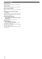
Yamaha RX-V2500 Owner's Manual - Page 17
Speaker connections, Di-pole speaker layout - thx
 |
View all Yamaha RX-V2500 manuals
Add to My Manuals
Save this manual to your list of manuals |
Page 17 highlights
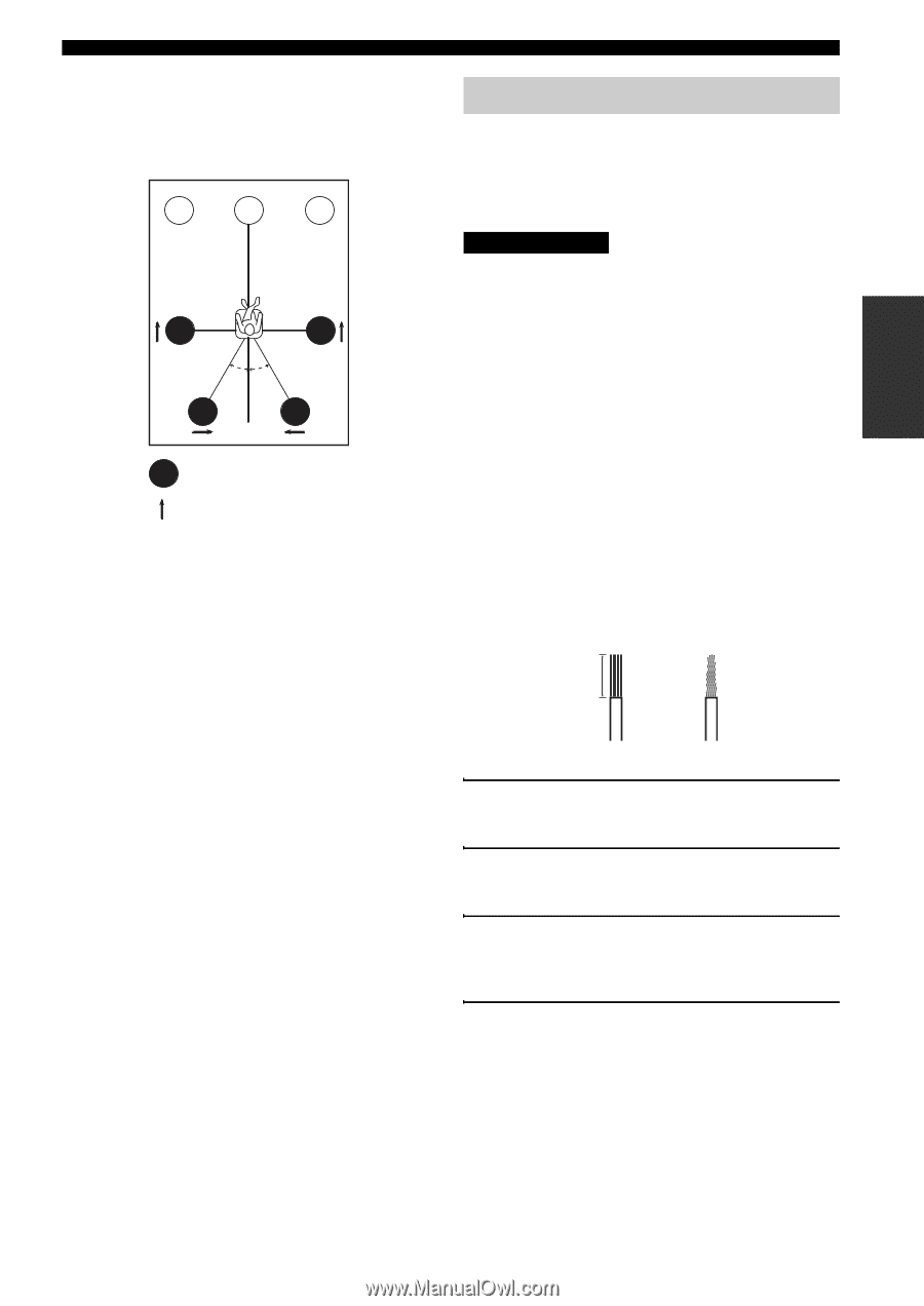
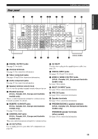
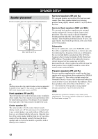
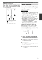
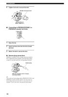
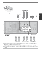
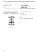
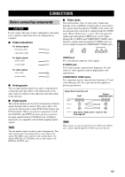
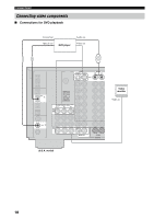
PREPARATION ■ Di-pole speaker layout Either di-pole or direct radiating speaker types can be used for THX surround. If you choose di-pole speakers, please place the surround and surround back speakers according to the speaker layout below. FL C FR SL SR 30˚ 30˚ SBL SBR :Di-pole speaker :Direction of di-pole speaker SPEAKER SETUP Speaker connections Be sure to connect the left channel (L), right channel (R), "+" (red) and "-" (black) properly. If the connections are faulty, no sound will be heard from the speakers, and if the polarity of the speaker connections is incorrect, the sound will be unnatural and lack bass. CAUTION • If you will use 6 ohm speakers, be sure to set this unit's speaker impedance setting to 6 ohms before using (see page 25). If you will use 8 ohm speakers, use this unit's initial setting for speaker impedance. • Before connecting the speakers, make sure that this unit is disconnected from the power source. • Do not let the bare speaker wires touch each other or do not let them touch any metal part of this unit. This could damage this unit and/or speakers. • Use magnetically shielded speakers. If this type of speaker still creates interference with the monitor, place the speakers away from the monitor. A speaker cord is actually a pair of insulated cables running side by side. One cable is colored or shaped differently, perhaps with a stripe, groove or ridges. Connect the striped (grooved, etc.) cable to the "+" (red) terminals on this unit and your speaker. Connect the plain cable to the "-" (black) terminals. 10 mm (3/8 in) 1 2 1 Remove approximately 10 mm (3/8 in) of insulation from each of the speaker cables. 2 Twist the exposed wires of the cable together to prevent short circuits. 3 Loosen the knob. The supplied speaker terminal wrench is useful for loosening or tightening knobs. 4 Insert one bare wire into the hole in the side of each terminal. 13
-
 1
1 -
2
-
3
-
4
-
5
-
6
-
7
-
8
-
9
-
10
-
11
-
 12
12 -
 13
13 -
 14
14 -
 15
15 -
 16
16 -
 17
17 -
 18
18 -
 19
19 -
 20
20 -
 21
21 -
 22
22 -
23
-
24
-
25
-
26
-
27
-
28
-
29
-
30
-
31
-
32
-
33
-
34
-
35
-
36
-
37
-
38
-
39
-
40
-
41
-
42
-
43
-
44
-
45
-
46
-
47
-
48
-
49
-
50
-
51
-
52
-
53
-
54
-
55
-
56
-
57
-
58
-
59
-
60
-
61
-
62
-
63
-
64
-
65
-
66
-
67
-
68
-
69
-
70
-
71
-
72
-
73
-
74
-
75
-
76
-
77
-
78
-
79
-
80
-
81
-
82
-
83
-
84
-
85
-
86
-
87
-
88
-
89
-
90
-
91
-
92
-
93
-
94
-
95
-
96
-
97
-
98
-
99
-
100
-
101
-
102
-
103
-
104
-
105
-
106
-
107
-
108
-
109
-
110
-
111
-
112
 |
 |