Brother International ZE-856A Instruction Manual - English and Spanish - Page 184
Adjusting the position of the thread trimming cam 856A only
 |
View all Brother International ZE-856A manuals
Add to My Manuals
Save this manual to your list of manuals |
Page 184 highlights
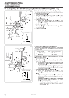
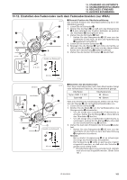
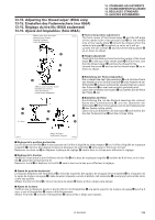
13. STANDARD ADJUSTMENTS 13. STANDARDEINSTELLUNGEN 13. REGLAGES STANDARD 13. AJUSTES ESTANDARES 13-13. Adjusting the position of the thread trimming cam (856A only) The knife unit q should already be installed in the correct way when the following adjustments are carried out. q 0.5 mm w r 1035S I Horizontal position adjustment 1. Tilt back the machine head. 2. Loosen the two screws w. 3. Move the stopper r to adjust so that the edge of the movable knife e is 0.5 mm inside the edge of the knife unit q. 4. Securely tighten the screws w. 5. Loosen the two set screws t and the two set screws y. 6. While pushing the thread trimming driving rod u by hand, adjust the horizontal position of the thread trim- ming cam !0 so that the roller o of the main lever i moves smoothly in and out of the straight section A of the groove in the thread trimming cam !.0 7. Provisionally tighten the two set screws t. 8. Place the set screw collar !1 firmly against the thread trim- ming cam !,0 and then securely tighten the two set screws y. t !1 A y i !0 o u 1036S 1037S I Rotating direction adjustment 1. While still pushing thread trimming driving rod u by hand, turn the machine pulley slowly by hand toward you until the reference line on the thread take-up lever !2 is aligned with the T mark on the face plate. Adjust U the position of the thread trimming cam !0 so that the knife begins to move at this point. !2 2. Securely tighten the two set screws t. 3. While still pushing thread trimming driving rod u by hand, turn the machine pulley slowly by hand toward you until the reference line on the thread take-up lever T is aligned with the T mark on the face plate. Check that the knife begins to move at this point, and that it re- turns when the reference line is aligned with the U mark. t !0 165 u 1038S ZE-855A,856A
-
 1
1 -
2
-
3
-
4
-
5
-
6
-
7
-
8
-
9
-
10
-
11
-
12
-
13
-
14
-
15
-
16
-
17
-
18
-
19
-
20
-
21
-
22
-
23
-
24
-
25
-
26
-
27
-
28
-
29
-
30
-
31
-
32
-
33
-
34
-
35
-
36
-
37
-
38
-
39
-
40
-
41
-
42
-
43
-
44
-
45
-
46
-
47
-
48
-
49
-
50
-
51
-
52
-
53
-
54
-
55
-
56
-
57
-
58
-
59
-
60
-
61
-
62
-
63
-
64
-
65
-
66
-
67
-
68
-
69
-
70
-
71
-
72
-
73
-
74
-
75
-
76
-
77
-
78
-
79
-
80
-
81
-
82
-
83
-
84
-
85
-
86
-
87
-
88
-
89
-
90
-
91
-
92
-
93
-
94
-
95
-
96
-
97
-
98
-
99
-
100
-
101
-
102
-
103
-
104
-
105
-
106
-
107
-
108
-
109
-
110
-
111
-
112
-
113
-
114
-
115
-
116
-
117
-
118
-
119
-
120
-
121
-
122
-
123
-
124
-
125
-
126
-
127
-
128
-
129
-
130
-
131
-
132
-
133
-
134
-
135
-
136
-
137
-
138
-
139
-
140
-
141
-
142
-
143
-
144
-
145
-
146
-
147
-
148
-
149
-
150
-
151
-
152
-
153
-
154
-
155
-
156
-
157
-
158
-
159
-
160
-
161
-
162
-
163
-
164
-
165
-
166
-
167
-
168
-
169
-
170
-
171
-
172
-
173
-
174
-
175
-
176
-
177
-
178
-
 179
179 -
 180
180 -
 181
181 -
 182
182 -
 183
183 -
 184
184 -
 185
185 -
 186
186 -
 187
187 -
 188
188 -
 189
189 -
190
-
191
-
192
-
193
-
194
-
195
-
196
-
197
-
198
-
199
-
200
-
201
-
202
-
203
-
204
-
205
-
206
-
207
-
208
-
209
-
210
-
211
-
212
-
213
-
214
-
215
-
216
-
217
-
218
-
219
-
220
-
221
-
222
-
223
-
224
-
225
-
226
-
227
-
228
-
229
-
230
-
231
-
232
-
233
-
234
-
235
-
236
-
237
-
238
-
239
-
240
-
241
-
242
-
243
-
244
-
245
-
246
-
247
-
248
 |
 |
