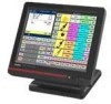
Casio QT 6600 Reference Manual - Page 14
SHIFT PLU 1, Menu shift 1 - cash register
 |
View all Casio QT 6600 manuals
Add to My Manuals
Save this manual to your list of manuals |
Page 14 highlights
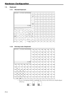
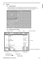
Hardware Configuration 1-4-3. Menu level display part contents SHIFT PLU 1 Shift PLU level (1 ~ 8) Menu shift 1 2nd@ Menu shift (1 ~ 15) 2nd unit Price level (1 ~ 2) 1-4-4. Main display brightness control LAN DISPLAY COM3 COM6 SCANNER COM2 COM5 PC/MODEM COM1 COM4 Brightness control 1-5. Cash drawer In case of connecting drawer, follow the procedure below. Connect the drawer. 1. Connect drawer connector (three color lead on drawer) to the terminal. 2. Connect frame drawer connector (green lead on drawer) to the terminal. Mount the cash register. 1. Attach 2 positioning screws bottom side of the terminal. 2. Mount the terminal on the top of the drawer, ensuring that the feet on the bottom of the terminal go into the holes on the drawer. R-14
-
 1
1 -
2
-
3
-
4
-
5
-
6
-
7
-
8
-
 9
9 -
 10
10 -
 11
11 -
 12
12 -
 13
13 -
 14
14 -
 15
15 -
 16
16 -
 17
17 -
 18
18 -
 19
19 -
20
-
21
-
22
-
23
-
24
-
25
-
26
-
27
-
28
-
29
-
30
-
31
-
32
-
33
-
34
-
35
-
36
-
37
-
38
-
39
-
40
-
41
-
42
-
43
-
44
-
45
-
46
-
47
-
48
-
49
-
50
-
51
-
52
-
53
-
54
-
55
-
56
-
57
-
58
-
59
-
60
-
61
-
62
-
63
-
64
-
65
-
66
-
67
-
68
-
69
-
70
-
71
-
72
-
73
-
74
-
75
-
76
-
77
-
78
-
79
-
80
-
81
-
82
-
83
-
84
-
85
-
86
-
87
-
88
-
89
-
90
-
91
-
92
-
93
-
94
-
95
-
96
-
97
-
98
-
99
-
100
-
101
-
102
-
103
-
104
-
105
-
106
-
107
-
108
-
109
-
110
-
111
-
112
-
113
-
114
-
115
-
116
-
117
-
118
-
119
-
120
-
121
-
122
-
123
-
124
-
125
-
126
-
127
-
128
-
129
-
130
-
131
-
132
-
133
-
134
-
135
-
136
-
137
-
138
-
139
-
140
-
141
-
142
-
143
-
144
-
145
-
146
-
147
-
148
-
149
-
150
-
151
-
152
-
153
-
154
-
155
-
156
-
157
-
158
-
159
-
160
-
161
-
162
-
163
-
164
-
165
-
166
-
167
-
168
-
169
-
170
-
171
-
172
-
173
-
174
-
175
-
176
-
177
-
178
-
179
-
180
-
181
-
182
-
183
-
184
-
185
-
186
-
187
-
188
-
189
-
190
-
191
-
192
-
193
-
194
-
195
-
196
-
197
-
198
-
199
-
200
-
201
-
202
-
203
-
204
-
205
-
206
-
207
-
208
-
209
-
210
-
211
-
212
-
213
-
214
-
215
-
216
-
217
-
218
-
219
-
220
-
221
-
222
-
223
-
224
-
225
-
226
-
227
-
228
-
229
-
230
-
231
-
232
-
233
-
234
-
235
-
236
-
237
-
238
-
239
-
240
 |
 |

R-14
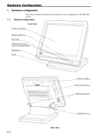
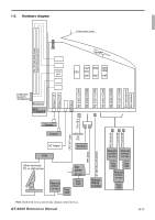
Hardware Configuration
1-5.
Cash drawer
In case of connecting drawer, follow the procedure below.
Connect the drawer.
1.
Connect drawer connector (three color lead on drawer) to the terminal.
2.
Connect frame drawer connector (green lead on drawer) to the terminal.
Mount the cash register.
1.
Attach 2 positioning screws bottom side of the terminal.
2.
Mount the terminal on the top of the drawer, ensuring that the feet on the bottom of the
terminal go into the holes on the drawer.
DISPLAY
SCANNER
PC/MODEM
COM3
COM6
COM2
COM5
COM1
COM4
LAN
1-4-4.
Main display brightness control
1-4-3.
Menu level display part contents
SHIFT PLU 1
Menu shift 1
2nd@
Shift PLU level (1 ~ 8)
Menu shift (1 ~ 15)
2nd unit Price level (1 ~ 2)
Brightness control