Cisco CISCO1401 Software Guide - Page 249
Bridge Normal Mode LED Indications, Ethernet, Status, Radio, Meaning
 |
UPC - 746320202785
View all Cisco CISCO1401 manuals
Add to My Manuals
Save this manual to your list of manuals |
Page 249 highlights
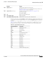
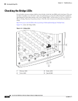
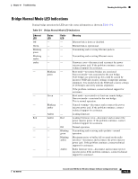
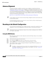
Chapter 19 Troubleshooting Checking the Bridge LEDs Bridge Normal Mode LED Indications During bridge operation the LEDs provide status information as shown in Table 19-1. Table 19-1 Bridge Normal Mode LED Indications Ethernet LED Off Green Blinking green Blinking amber amber - - - - Red - - - - Status LED - - - Radio LED - - - Meaning Ethernet link is down or disabled. Ethernet link is operational. Transmitting and receiving Ethernet packets. - - Transmitting and receiving Ethernet errors. - Blinking green Green Blinking amber Amber Amber - - - - - - - - - Red Off Blinking green Blinking amber Amber Firmware error-disconnect and reconnect the power injector power jack. If the problem continues, contact technical support for assistance. Root mode-no remote bridges are associated. Non-root mode-not associated to the root bridge. If all bridges are powered up, this could be caused by incorrect SSID and security settings or improper antenna alignment. You should check the SSID and security settings of all bridges and verify antenna alignment. If the problem continues, contact technical support for assistance. Root mode-associated to at least one remote bridge. Non-root mode-associated to the root bridge. This is normal operation. General warning-disconnect and reconnect the power injector power jack. If the problem continues, contact technical support for assistance. Loading firmware. Loading Firmware error-disconnect and reconnect the power injector power. If the problem continues, contact technical support for assistance. Normal operation. Transmitting and receiving radio packets-normal operation. Maximum retries or buffer full occurred on the radio interface-disconnect and reconnect the power injector power jack. If the problem continues, contact technical support for assistance. Radio firmware error-disconnect and reconnect power injector power.If the problem continues, contact technical support for assistance. OL-4059-01 Cisco Aironet 1400 Series Wireless Bridges Software Configuration Guide 19-3
-
 1
1 -
2
-
3
-
4
-
5
-
6
-
7
-
8
-
9
-
10
-
11
-
12
-
13
-
14
-
15
-
16
-
17
-
18
-
19
-
20
-
21
-
22
-
23
-
24
-
25
-
26
-
27
-
28
-
29
-
30
-
31
-
32
-
33
-
34
-
35
-
36
-
37
-
38
-
39
-
40
-
41
-
42
-
43
-
44
-
45
-
46
-
47
-
48
-
49
-
50
-
51
-
52
-
53
-
54
-
55
-
56
-
57
-
58
-
59
-
60
-
61
-
62
-
63
-
64
-
65
-
66
-
67
-
68
-
69
-
70
-
71
-
72
-
73
-
74
-
75
-
76
-
77
-
78
-
79
-
80
-
81
-
82
-
83
-
84
-
85
-
86
-
87
-
88
-
89
-
90
-
91
-
92
-
93
-
94
-
95
-
96
-
97
-
98
-
99
-
100
-
101
-
102
-
103
-
104
-
105
-
106
-
107
-
108
-
109
-
110
-
111
-
112
-
113
-
114
-
115
-
116
-
117
-
118
-
119
-
120
-
121
-
122
-
123
-
124
-
125
-
126
-
127
-
128
-
129
-
130
-
131
-
132
-
133
-
134
-
135
-
136
-
137
-
138
-
139
-
140
-
141
-
142
-
143
-
144
-
145
-
146
-
147
-
148
-
149
-
150
-
151
-
152
-
153
-
154
-
155
-
156
-
157
-
158
-
159
-
160
-
161
-
162
-
163
-
164
-
165
-
166
-
167
-
168
-
169
-
170
-
171
-
172
-
173
-
174
-
175
-
176
-
177
-
178
-
179
-
180
-
181
-
182
-
183
-
184
-
185
-
186
-
187
-
188
-
189
-
190
-
191
-
192
-
193
-
194
-
195
-
196
-
197
-
198
-
199
-
200
-
201
-
202
-
203
-
204
-
205
-
206
-
207
-
208
-
209
-
210
-
211
-
212
-
213
-
214
-
215
-
216
-
217
-
218
-
219
-
220
-
221
-
222
-
223
-
224
-
225
-
226
-
227
-
228
-
229
-
230
-
231
-
232
-
233
-
234
-
235
-
236
-
237
-
238
-
239
-
240
-
241
-
242
-
243
-
 244
244 -
 245
245 -
 246
246 -
 247
247 -
 248
248 -
 249
249 -
 250
250 -
 251
251 -
 252
252 -
 253
253 -
 254
254 -
255
-
256
-
257
-
258
-
259
-
260
-
261
-
262
-
263
-
264
-
265
-
266
-
267
-
268
-
269
-
270
-
271
-
272
-
273
-
274
-
275
-
276
-
277
-
278
-
279
-
280
-
281
-
282
-
283
-
284
-
285
-
286
 |
 |
