Cisco CISCO1401 Software Guide - Page 251
Uplink Activity, Injector Status, Ethernet Activity, Description, Power Injector LEDs
 |
UPC - 746320202785
View all Cisco CISCO1401 manuals
Add to My Manuals
Save this manual to your list of manuals |
Page 251 highlights
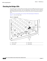
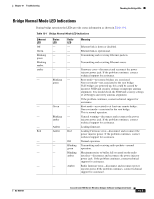
Chapter 19 Troubleshooting The power injector LEDs are shown in Figure 19-2. Figure 19-2 Power Injector LEDs 7 68 IpIIpspsasamammyyyoopopspsusumumm Power Injector LEDs OL-4059-01 88820 1 3 2 45 1 Power jack (+48 VDC) 2 Power LED 3 Power injector dual-coax ports (F-Type connectors) 4 Mode button 5 Ethernet port (RJ-45 connector) 6 Ethernet Activity LED 7 Injector Status LED 8 Uplink Activity LED The power injector LED indications are shown in Table 19-3. Table 19-3 Power Injector LED Indications Uplink Activity - - - - Off Green Injector Status - - - - - - Ethernet Activity Description Off Wired LAN Ethernet link is not active. Green Wired LAN Ethernet link is operational. Blinking Green Transmitting and receiving packets over the wired LAN Ethernet link. Amber Power injector internal memory error-disconnect and reconnect the power injector power plug. If the problem continues, contact technical support for assistance. - Link between power injector and bridge is not active. This might be caused by improper connections or a defective cable or connector. Verify that the dual-coax cables are connected correctly to the power injector, grounding block, and bridge. If the cables are connected correctly, contact technical support for assistance. - Link between power injector and bridge is operational. Cisco Aironet 1400 Series Wireless Bridges Software Configuration Guide 19-5
-
 1
1 -
2
-
3
-
4
-
5
-
6
-
7
-
8
-
9
-
10
-
11
-
12
-
13
-
14
-
15
-
16
-
17
-
18
-
19
-
20
-
21
-
22
-
23
-
24
-
25
-
26
-
27
-
28
-
29
-
30
-
31
-
32
-
33
-
34
-
35
-
36
-
37
-
38
-
39
-
40
-
41
-
42
-
43
-
44
-
45
-
46
-
47
-
48
-
49
-
50
-
51
-
52
-
53
-
54
-
55
-
56
-
57
-
58
-
59
-
60
-
61
-
62
-
63
-
64
-
65
-
66
-
67
-
68
-
69
-
70
-
71
-
72
-
73
-
74
-
75
-
76
-
77
-
78
-
79
-
80
-
81
-
82
-
83
-
84
-
85
-
86
-
87
-
88
-
89
-
90
-
91
-
92
-
93
-
94
-
95
-
96
-
97
-
98
-
99
-
100
-
101
-
102
-
103
-
104
-
105
-
106
-
107
-
108
-
109
-
110
-
111
-
112
-
113
-
114
-
115
-
116
-
117
-
118
-
119
-
120
-
121
-
122
-
123
-
124
-
125
-
126
-
127
-
128
-
129
-
130
-
131
-
132
-
133
-
134
-
135
-
136
-
137
-
138
-
139
-
140
-
141
-
142
-
143
-
144
-
145
-
146
-
147
-
148
-
149
-
150
-
151
-
152
-
153
-
154
-
155
-
156
-
157
-
158
-
159
-
160
-
161
-
162
-
163
-
164
-
165
-
166
-
167
-
168
-
169
-
170
-
171
-
172
-
173
-
174
-
175
-
176
-
177
-
178
-
179
-
180
-
181
-
182
-
183
-
184
-
185
-
186
-
187
-
188
-
189
-
190
-
191
-
192
-
193
-
194
-
195
-
196
-
197
-
198
-
199
-
200
-
201
-
202
-
203
-
204
-
205
-
206
-
207
-
208
-
209
-
210
-
211
-
212
-
213
-
214
-
215
-
216
-
217
-
218
-
219
-
220
-
221
-
222
-
223
-
224
-
225
-
226
-
227
-
228
-
229
-
230
-
231
-
232
-
233
-
234
-
235
-
236
-
237
-
238
-
239
-
240
-
241
-
242
-
243
-
244
-
245
-
 246
246 -
 247
247 -
 248
248 -
 249
249 -
 250
250 -
 251
251 -
 252
252 -
 253
253 -
 254
254 -
 255
255 -
 256
256 -
257
-
258
-
259
-
260
-
261
-
262
-
263
-
264
-
265
-
266
-
267
-
268
-
269
-
270
-
271
-
272
-
273
-
274
-
275
-
276
-
277
-
278
-
279
-
280
-
281
-
282
-
283
-
284
-
285
-
286
 |
 |
