Cisco CISCO1401 Software Guide - Page 252
Checking Power
 |
UPC - 746320202785
View all Cisco CISCO1401 manuals
Add to My Manuals
Save this manual to your list of manuals |
Page 252 highlights
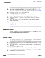
Checking Power Chapter 19 Troubleshooting Table 19-3 Power Injector LED Indications (continued) Uplink Activity Injector Status Ethernet Activity Description Blinking Green - - Transmitting and receiving Ethernet packets between the power injector and the bridge. Amber - - Power injector internal memory error-disconnect and reconnect the power injector power plug. If the problem continues, contact technical support for assistance. - Green - Bridge successfully passed Power On Self Test (POST) and loaded the IOS image. - Blinking Green - Bridge power is active and the bridge is loading IOS image or POST operation has started. - Blinking Amber -- Bridge has not been detected and bridge power is not active. This might be caused by bad connections or a defective cable or connector. Verify that the dual-coax cables are connected correctly to the power injector, grounding block, and bridge. If the cables are connected correctly, contact technical support for assistance. Amber Amber Amber Power injector internal memory error-disconnect and reconnect the power injector power plug. If the problem continues, contact technical support for assistance. Off Amber Off Bridge is resetting the configuration to defaults; mode button has been depressed more than 2 seconds but less than 20 seconds. - Red - Image recovery mode, downloading new image; mode button pressed more than 20 seconds. Red Red Red Power injector internal memory error-disconnect and reconnect the power injector power plug. If the problem continues, contact technical support for assistance. Checking Power You can verify the availability of power to the bridge by checking the power injector LEDs (see Figure 19-2): • Power LED - Green color indicates 48 VDC is available to the power injector (see Figure 19-2). - Off indicates 48 VDC is not available to the power injector-verify that the power module is connected to the power injector and to an AC receptacle and that AC power is available. • Uplink Activity LED - Green or blinking green color indicates the bridge is operating. 19-6 Cisco Aironet 1400 Series Wireless Bridges Software Configuration Guide OL-4059-01
-
 1
1 -
2
-
3
-
4
-
5
-
6
-
7
-
8
-
9
-
10
-
11
-
12
-
13
-
14
-
15
-
16
-
17
-
18
-
19
-
20
-
21
-
22
-
23
-
24
-
25
-
26
-
27
-
28
-
29
-
30
-
31
-
32
-
33
-
34
-
35
-
36
-
37
-
38
-
39
-
40
-
41
-
42
-
43
-
44
-
45
-
46
-
47
-
48
-
49
-
50
-
51
-
52
-
53
-
54
-
55
-
56
-
57
-
58
-
59
-
60
-
61
-
62
-
63
-
64
-
65
-
66
-
67
-
68
-
69
-
70
-
71
-
72
-
73
-
74
-
75
-
76
-
77
-
78
-
79
-
80
-
81
-
82
-
83
-
84
-
85
-
86
-
87
-
88
-
89
-
90
-
91
-
92
-
93
-
94
-
95
-
96
-
97
-
98
-
99
-
100
-
101
-
102
-
103
-
104
-
105
-
106
-
107
-
108
-
109
-
110
-
111
-
112
-
113
-
114
-
115
-
116
-
117
-
118
-
119
-
120
-
121
-
122
-
123
-
124
-
125
-
126
-
127
-
128
-
129
-
130
-
131
-
132
-
133
-
134
-
135
-
136
-
137
-
138
-
139
-
140
-
141
-
142
-
143
-
144
-
145
-
146
-
147
-
148
-
149
-
150
-
151
-
152
-
153
-
154
-
155
-
156
-
157
-
158
-
159
-
160
-
161
-
162
-
163
-
164
-
165
-
166
-
167
-
168
-
169
-
170
-
171
-
172
-
173
-
174
-
175
-
176
-
177
-
178
-
179
-
180
-
181
-
182
-
183
-
184
-
185
-
186
-
187
-
188
-
189
-
190
-
191
-
192
-
193
-
194
-
195
-
196
-
197
-
198
-
199
-
200
-
201
-
202
-
203
-
204
-
205
-
206
-
207
-
208
-
209
-
210
-
211
-
212
-
213
-
214
-
215
-
216
-
217
-
218
-
219
-
220
-
221
-
222
-
223
-
224
-
225
-
226
-
227
-
228
-
229
-
230
-
231
-
232
-
233
-
234
-
235
-
236
-
237
-
238
-
239
-
240
-
241
-
242
-
243
-
244
-
245
-
246
-
 247
247 -
 248
248 -
 249
249 -
 250
250 -
 251
251 -
 252
252 -
 253
253 -
 254
254 -
 255
255 -
 256
256 -
 257
257 -
258
-
259
-
260
-
261
-
262
-
263
-
264
-
265
-
266
-
267
-
268
-
269
-
270
-
271
-
272
-
273
-
274
-
275
-
276
-
277
-
278
-
279
-
280
-
281
-
282
-
283
-
284
-
285
-
286
 |
 |
