Cisco CISCO776 Installation Guide - Page 39
Connecting the ISDN Line
 |
View all Cisco CISCO776 manuals
Add to My Manuals
Save this manual to your list of manuals |
Page 39 highlights
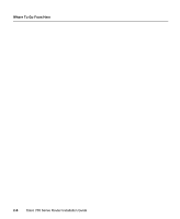
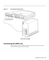
Figure 3-1 Connecting the Ethernet Cable CONFIG 4 3 10BA2 SET CISCO 776 1 ISDN S/T ISDN U Connect yellow cable to yellow Ethernet port S0 NT-1 +-350VV------10.5.2AA++/-/-52%5% ETH 17259 SER 0 OK LAN AUX Connect other end of cable to server, PC, or workstation Connecting the ISDN Line The procedure to connect an ISDN line depends on the router and in some cases your location. The following sections describe each. Installing Your Router 3-3
-
 1
1 -
2
-
3
-
4
-
5
-
6
-
7
-
8
-
9
-
10
-
11
-
12
-
13
-
14
-
15
-
16
-
17
-
18
-
19
-
20
-
21
-
22
-
23
-
24
-
25
-
26
-
27
-
28
-
29
-
30
-
31
-
32
-
33
-
 34
34 -
 35
35 -
 36
36 -
 37
37 -
 38
38 -
 39
39 -
 40
40 -
 41
41 -
 42
42 -
 43
43 -
 44
44 -
45
-
46
-
47
-
48
-
49
-
50
-
51
-
52
-
53
-
54
-
55
-
56
-
57
-
58
-
59
-
60
-
61
-
62
-
63
-
64
-
65
-
66
-
67
-
68
-
69
-
70
-
71
-
72
-
73
-
74
-
75
-
76
-
77
-
78
-
79
-
80
-
81
-
82
-
83
-
84
-
85
-
86
-
87
-
88
-
89
-
90
-
91
-
92
-
93
-
94
-
95
-
96
-
97
-
98
-
99
-
100
-
101
-
102
-
103
-
104
-
105
-
106
-
107
-
108
-
109
-
110
-
111
-
112
-
113
-
114
-
115
-
116
-
117
-
118
 |
 |

Installing Your Router
3-3
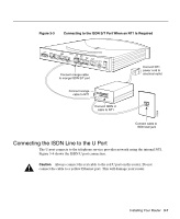
Figure 3-1
Connecting the Ethernet Cable
Connecting the ISDN Line
The procedure to connect an ISDN line depends on the router and in some cases your
location. The following sections describe each.
CONFIG
1
+5V ---1.5A +/-5%
-30V--- 0.2A +/-25%
S
0
NT-1
ISDN U
ISDN S/T
10BASET
CISCO 776
2
3
4
17259
AUX
SER 0
ETH
OK
LAN
Connect other end of cable
to server, PC, or workstation
Connect yellow cable
to yellow Ethernet port