Cisco CISCO776 Installation Guide - Page 46
Verifying Installation, The LAN, CH1, and CH2 LEDs each have companion RDX and TDX LEDs. The RDX
 |
View all Cisco CISCO776 manuals
Add to My Manuals
Save this manual to your list of manuals |
Page 46 highlights
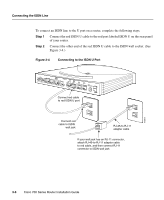
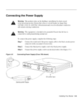
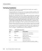
Verifying Installation Verifying Installation When the router is powered on, it is automatically booted, and the router attempts to establish links to the LAN and the WAN. Compare the LED states with known activity. For example, all LEDs should blink at least once during the boot process, which takes a few minutes. Once the router is booted, you can verify your connections by using the LEDs. The LAN, CH1, and CH2 LEDs each have companion RDX and TDX LEDs. The RDX and TDX LEDs indicate traffic on the respective channels. Using an application such as a Web browser, verify that the router is receiving data from the WAN. When you access a Web page on the network, the router indicates the transfer of data by turning on the LAN LED and blinking the companion RDX and TDX LEDs. The CH1 LED also turns on and the companion RDX and TDX LEDs blink. The CH2 LED might turn on, depending on the amount of traffic. If the LEDs do not behave as expected, check the physical connections. Brief descriptions of the LED states as they relate to the physical connections are provided in Table 3-1. All the LEDs are listed, but each router model has a different subset of LEDs. If your connections are correct and the LEDs are not in the correct state, it might be because the router or PC is not yet configured. If your router is configured and the states are not correct, see Chapter 5, "Troubleshooting Cisco 700 Series Routers." Table 3-1 LED RDY NT1 LINE LAN Verifying the Connections Connection Power ISDN U port ISDN U or S/T port Ethernet Normal Pattern On when the router is powered on. Off when the router is powered off. On when connected. Blinks when not connected. On when connected. Off when not connected. On for 1 minute after boot. Off if there is no traffic on the LAN for 1 minute. 3-10 Cisco 700 Series Router Installation Guide
-
 1
1 -
2
-
3
-
4
-
5
-
6
-
7
-
8
-
9
-
10
-
11
-
12
-
13
-
14
-
15
-
16
-
17
-
18
-
19
-
20
-
21
-
22
-
23
-
24
-
25
-
26
-
27
-
28
-
29
-
30
-
31
-
32
-
33
-
34
-
35
-
36
-
37
-
38
-
39
-
40
-
 41
41 -
 42
42 -
 43
43 -
 44
44 -
 45
45 -
 46
46 -
 47
47 -
 48
48 -
 49
49 -
 50
50 -
 51
51 -
52
-
53
-
54
-
55
-
56
-
57
-
58
-
59
-
60
-
61
-
62
-
63
-
64
-
65
-
66
-
67
-
68
-
69
-
70
-
71
-
72
-
73
-
74
-
75
-
76
-
77
-
78
-
79
-
80
-
81
-
82
-
83
-
84
-
85
-
86
-
87
-
88
-
89
-
90
-
91
-
92
-
93
-
94
-
95
-
96
-
97
-
98
-
99
-
100
-
101
-
102
-
103
-
104
-
105
-
106
-
107
-
108
-
109
-
110
-
111
-
112
-
113
-
114
-
115
-
116
-
117
-
118
 |
 |
