Cisco CISCO776 Installation Guide - Page 84
Power Connector, Common Port Assignments
 |
View all Cisco CISCO776 manuals
Add to My Manuals
Save this manual to your list of manuals |
Page 84 highlights
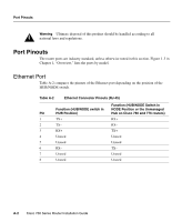
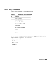
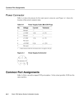
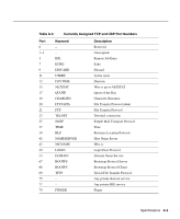
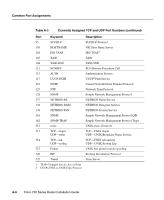
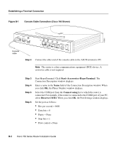
Common Port Assignments Power Connector Table A-4 shows the pinouts for the router power connector, and, Figure A-1 shows the location of the power connector pins. Table A-4 Power Supply Cable (Mini DIN Plug) Pin Voltage 1 Ground Current -1 Tolerance - 2 +5 VDC 1.5A +/- 5% 3 Ground - - 4 +5 VDC 1.5A +/- 5% 5 Not used - - 6 +30 VDC 0.2A +/- 25% 7 Not used - - 1 A dash indicates that the information does not apply to the pin. Figure A-1 Power Supply Comnnector 7 5 6 3 4 1 2 H6089 Common Port Assignments Table A-4 lists currently assigned TCP port numbers. To the extent possible, UDP uses the same numbers. A-4 Cisco 700 Series Router Installation Guide
-
 1
1 -
2
-
3
-
4
-
5
-
6
-
7
-
8
-
9
-
10
-
11
-
12
-
13
-
14
-
15
-
16
-
17
-
18
-
19
-
20
-
21
-
22
-
23
-
24
-
25
-
26
-
27
-
28
-
29
-
30
-
31
-
32
-
33
-
34
-
35
-
36
-
37
-
38
-
39
-
40
-
41
-
42
-
43
-
44
-
45
-
46
-
47
-
48
-
49
-
50
-
51
-
52
-
53
-
54
-
55
-
56
-
57
-
58
-
59
-
60
-
61
-
62
-
63
-
64
-
65
-
66
-
67
-
68
-
69
-
70
-
71
-
72
-
73
-
74
-
75
-
76
-
77
-
78
-
 79
79 -
 80
80 -
 81
81 -
 82
82 -
 83
83 -
 84
84 -
 85
85 -
 86
86 -
 87
87 -
 88
88 -
 89
89 -
90
-
91
-
92
-
93
-
94
-
95
-
96
-
97
-
98
-
99
-
100
-
101
-
102
-
103
-
104
-
105
-
106
-
107
-
108
-
109
-
110
-
111
-
112
-
113
-
114
-
115
-
116
-
117
-
118
 |
 |

Cisco 700 Series Router Installation Guide
Common Port Assignments
A-4
Power Connector
Table A-4 shows the pinouts for the router power connector, and, Figure A-1 shows the
location of the power connector pins.
Figure A-1
Power Supply Comnnector
Common Port Assignments
Table A-4 lists currently assigned TCP port numbers. To the extent possible, UDP uses the
same numbers.
Table A-4
Power Supply Cable (Mini DIN Plug)
Pin
Voltage
Current
Tolerance
1
Ground
–
1
1
A dash indicates that the information does not apply to the pin.
–
2
+5 VDC
1.5A
+/– 5%
3
Ground
–
–
4
+5 VDC
1.5A
+/– 5%
5
Not used
–
–
6
+30 VDC
0.2A
+/– 25%
7
Not used
–
–
1
3
5
2
4
6
7
H6089