Cisco CISCO776 Installation Guide - Page 78
NT1 and the ISDN Ports, HUB/NODE Switch
 |
View all Cisco CISCO776 manuals
Add to My Manuals
Save this manual to your list of manuals |
Page 78 highlights
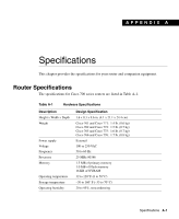
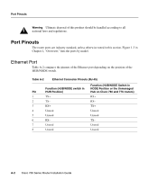
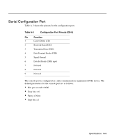
HUB/NODE Switch NT1 and the ISDN Ports Commonly, telephone carriers use a four-wire network within their system. The wiring in your home or business is a two-wire local loop. A Network Termination 1 (NT1) device connects the telephone carrier four-wire network to a two-wire local loop. Inside North America, it is common to find an NT1 built into a network device. Outside North America, the telephone carrier or the user must provide an external NT1. To use the internal NT1, the telephone carrier line is connected to an ISDN U port. If an external NT1 is required, the telephone carrier line is connected the ISDN U port on the NT1, and the router's ISDN S/T port is connected to the ISDN S/T port on the NT1. HUB/NODE Switch The Ethernet ports on hubs are wired differently than the Ethernet ports on nodes. This allows the devices to communicate with a straight-through Ethernet cable. Basically, transmitted data must be sent from the transmit pin on one device to the receive pin on the other device, and vice versa. Nodes connected to hubs handle this crossover internally. If the signal does not cross over, the transmitted data is sent from the transmit pin on the sending device to the transmit pin on the receiving device, and communications fails. To connect two nodes or two hubs, the signal must be crossed externally. Usually this is accomplished using an Ethernet crossover cable. The pins of a crossover cable have been rewired so the transmit pins are connected to the receive pins, as shown in Figure 6-1. 6-4 Cisco 700 Series Router Installation Guide
-
 1
1 -
2
-
3
-
4
-
5
-
6
-
7
-
8
-
9
-
10
-
11
-
12
-
13
-
14
-
15
-
16
-
17
-
18
-
19
-
20
-
21
-
22
-
23
-
24
-
25
-
26
-
27
-
28
-
29
-
30
-
31
-
32
-
33
-
34
-
35
-
36
-
37
-
38
-
39
-
40
-
41
-
42
-
43
-
44
-
45
-
46
-
47
-
48
-
49
-
50
-
51
-
52
-
53
-
54
-
55
-
56
-
57
-
58
-
59
-
60
-
61
-
62
-
63
-
64
-
65
-
66
-
67
-
68
-
69
-
70
-
71
-
72
-
 73
73 -
 74
74 -
 75
75 -
 76
76 -
 77
77 -
 78
78 -
 79
79 -
 80
80 -
 81
81 -
 82
82 -
 83
83 -
84
-
85
-
86
-
87
-
88
-
89
-
90
-
91
-
92
-
93
-
94
-
95
-
96
-
97
-
98
-
99
-
100
-
101
-
102
-
103
-
104
-
105
-
106
-
107
-
108
-
109
-
110
-
111
-
112
-
113
-
114
-
115
-
116
-
117
-
118
 |
 |
