Cisco CISCO776 Installation Guide - Page 43
Connecting the ISDN Line to the U Port,
 |
View all Cisco CISCO776 manuals
Add to My Manuals
Save this manual to your list of manuals |
Page 43 highlights
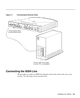
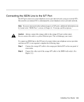
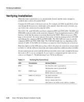
Figure 3-3 Connecting to the ISDN S/T Port When an NT1 Is Required CONFIG 4 3 10BA2 SET CISCO 776 1 ISDN S/T ISDN U S0 NT-1 +-350VV------10.5.2AA++/-/-52%5% Connect orange cable to orange ISDN S/T port Connect orange cable to NT1 Connect ISDN U cable to NT1 Connect NT1 power cord to electrical outlet Connect cable to ISDN wall jack 17258 Connecting the ISDN Line to the U Port The U port connects to the telephone service provider network using the internal NT1. Figure 3-4 shows the ISDN U port connection. Caution Always connect the red cable to the red U port on the router. Do not connect the cable to a yellow Ethernet port. This will damage your router. Installing Your Router 3-7
-
 1
1 -
2
-
3
-
4
-
5
-
6
-
7
-
8
-
9
-
10
-
11
-
12
-
13
-
14
-
15
-
16
-
17
-
18
-
19
-
20
-
21
-
22
-
23
-
24
-
25
-
26
-
27
-
28
-
29
-
30
-
31
-
32
-
33
-
34
-
35
-
36
-
37
-
 38
38 -
 39
39 -
 40
40 -
 41
41 -
 42
42 -
 43
43 -
 44
44 -
 45
45 -
 46
46 -
 47
47 -
 48
48 -
49
-
50
-
51
-
52
-
53
-
54
-
55
-
56
-
57
-
58
-
59
-
60
-
61
-
62
-
63
-
64
-
65
-
66
-
67
-
68
-
69
-
70
-
71
-
72
-
73
-
74
-
75
-
76
-
77
-
78
-
79
-
80
-
81
-
82
-
83
-
84
-
85
-
86
-
87
-
88
-
89
-
90
-
91
-
92
-
93
-
94
-
95
-
96
-
97
-
98
-
99
-
100
-
101
-
102
-
103
-
104
-
105
-
106
-
107
-
108
-
109
-
110
-
111
-
112
-
113
-
114
-
115
-
116
-
117
-
118
 |
 |

Installing Your Router
3-7
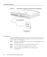
Figure 3-3
Connecting to the ISDN S/T Port When an NT1 Is Required
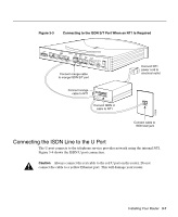
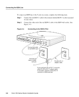
Connecting the ISDN Line to the U Port
The U port connects to the telephone service provider network using the internal NT1.
Figure 3-4 shows the ISDN U port connection.
Caution
Always connect the red cable to the red U port on the router. Do not
connect the cable to a yellow Ethernet port. This will damage your router.
CONFIG
1
+5V ---1.5A +/-5%
-30V--- 0.2A +/-25%
S
0
NT-1
ISDN U
ISDN S/T
10BASET
CISCO 776
2
3
4
17258
Connect orange cable
to orange ISDN S/T port
Connect orange
cable to NT1
Connect ISDN U
cable to NT1
Connect cable to
ISDN wall jack
Connect NT1
power cord to
electrical outlet