Cisco SRW2008P User Guide - Page 49
Point-to-Point Admin Status
 |
UPC - 745883571024
View all Cisco SRW2008P manuals
Add to My Manuals
Save this manual to your list of manuals |
Page 49 highlights
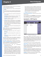
Chapter 5 Advanced Configuration network topologies that allow a faster STP convergence without creating forwarding loops. Interface Displays the port or LAG on which Rapid STP is enabled. Role Indicates the port role assigned by the STP algorithm in order to provide to STP paths. The possible field values are: •• Root Provides the lowest cost path to forward packets to root switch. •• Designated Indicates that the port or LAG via which the designated switch is attached to the LAN. •• Alternate Provides an alternate path to the root switch from the root interface. •• Backup Provides a backup path to the designated port path toward the Spanning Tree leaves. Backup ports occur only when two ports are connected in a loop by a point-to-point link. Backup ports also occur when a LAN has two or more connections connected to a shared segment. •• Disabled Indicates the port is not participating in the Spanning Tree. Mode Indicates the current Spanning Tree mode. The Spanning Tree mode is selected in the Global STP screen. The possible field values are: •• Classic STP Indicates that Classic STP is enabled on the device. •• Rapid STP Indicates that Rapid STP is enabled on the device. •• Multiple STP Indicates that Multiple STP is enabled on the device. Fast Link Indicates if Fast Link is enabled or disabled for the port or LAG. If Fast Link is enabled for a port, the port is automatically placed in the forwarding state. Port State Indicates if RSTP is enabled on the interface. Point-to-Point Admin Status Indicates if a point-to-point links are established, or permits the device to establish a point-to-point link. The possible field values are: •• Auto Point-to-point links are automatically established by the device. •• Enabled Enables the device to establish a point-topoint link. To establish communications over a pointto-point link, the originating PPP first sends Link Control Protocol (LCP) packets to configure and test the data link. After a link is established and optional facilities are negotiated as needed by the LCP, the originating PPP sends Network Control Protocols (NCP) packets to select and configure one or more network layer protocols. When each of the chosen network 8-Port 10/100/1000 Gigabit Switch with Webview layer protocols has been configured, packets from each network layer protocol can be sent over the link. The link remains configured for communications until explicit LCP or NCP packets close the link, or until some external event occurs. This is the actual switch port link type. It may differ from the administrative state. •• Disabled Disables point-to-point link. Point-to-Point Oper Status Indicates the Point-to-Point operating state. To run a migration test, press Activate next to the Activate Protocol Migration Test field. The test sends Link Control Protocol (LCP) packets to test if a data link is enabled. Spanning Tree > MSTP Properties Spanning Tree > MSTP Properties MSTP provides differing load balancing scenarios. For example, while port A is blocked in one STP instance, the same port is placed in the Forwarding State in another STP instance. The MSTP Properties screen contains information for defining global MSTP settings, including region names, MSTP revisions, and maximum hops. The MSTP Properties screen contains the following fields: Region Name Provides a user-defined STP region name. Revision Defines unsigned 16-bit number that identifies the revision of the current MST configuration. The revision number is required as part of the MST configuration. The possible field range 0-65535. Max Hops Indicates the total number of hops that occur in a specific region before the BPDU is discarded. Once the BPDU is discarded, the port information is aged out. The possible field range is 1-40. The field default is 20 hops. IST Master Identifies the Spanning Tree Master instance. The IST Master is the specified instance root. 43
-
 1
1 -
2
-
3
-
4
-
5
-
6
-
7
-
8
-
9
-
10
-
11
-
12
-
13
-
14
-
15
-
16
-
17
-
18
-
19
-
20
-
21
-
22
-
23
-
24
-
25
-
26
-
27
-
28
-
29
-
30
-
31
-
32
-
33
-
34
-
35
-
36
-
37
-
38
-
39
-
40
-
41
-
42
-
43
-
 44
44 -
 45
45 -
 46
46 -
 47
47 -
 48
48 -
 49
49 -
 50
50 -
 51
51 -
 52
52 -
 53
53 -
 54
54 -
55
-
56
-
57
-
58
-
59
-
60
-
61
-
62
-
63
-
64
-
65
-
66
-
67
-
68
-
69
-
70
-
71
-
72
-
73
-
74
-
75
-
76
-
77
-
78
-
79
-
80
-
81
 |
 |
