Cub Cadet ZT1 42 FAB Operation Manual - Page 15
Throttle/Choke Control Lever, Throttle, Control or Electronic Governor Control, If Equipped²
 |
View all Cub Cadet ZT1 42 FAB manuals
Add to My Manuals
Save this manual to your list of manuals |
Page 15 highlights
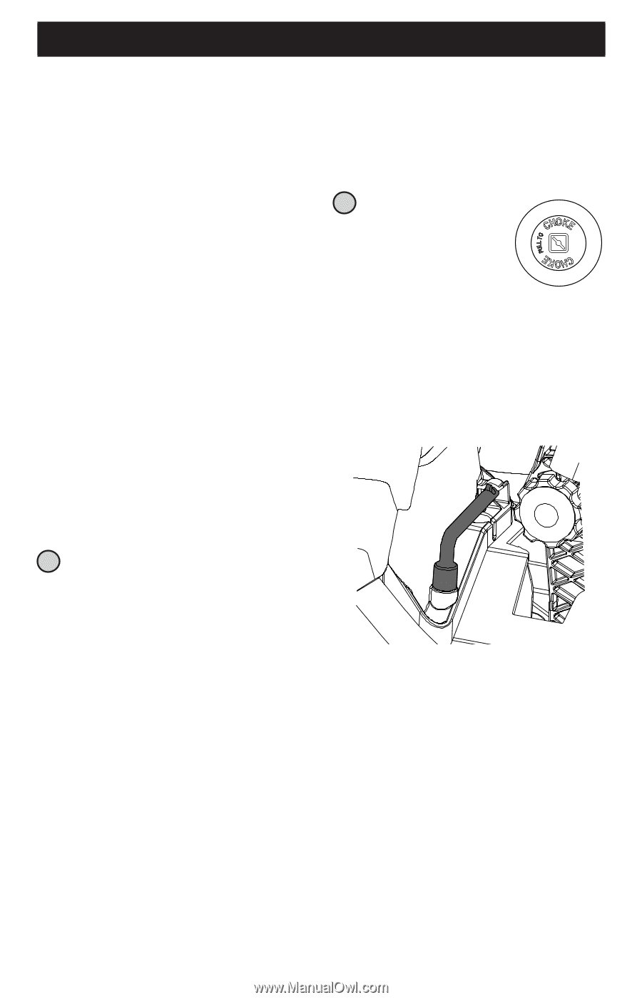
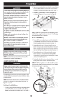
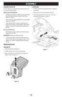
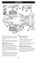
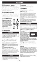
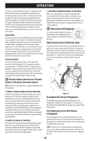
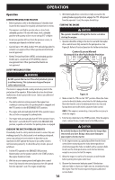
OPERATION The LCD screen will alternate the letters "LO" followed by "OIL", followed by the meter's accumulated time, which indicates the engine has low oil pressure. This is common when starting an engine. The indicator will remain active until the engine sufficiently builds pressure after starting. If it remains on with the engine at full speed and after a few minutes of operation, stop the tractor immediately and check the engine oil level and add as instructed in the Engine Operator's Manual. If the oil level is correct and the indicator persists, contact an authorized service dealer. LOW BATTERY At startup, the battery voltage will briefly display, then changes to accumulated hours. The letters "LO" followed by the letters "BATT" will display, followed by the meter's accumulated time. "LO/BATT/TIME" is displayed on the LCD when the voltage drops below 11.5 volts. When this occurs, the battery is in need of a charge or the engine's charging system is not generating sufficient amperage. Charge the battery as instructed in the Charging the Battery section of this manual or have the charging system checked by your local service dealer. AIR FILTER SERVICE The LCD screen will display the letters "CLN" followed by the letters "AIR", followed by "FILT", followed by the meter's accumulated time. "CLN/AIR/FILT/TIME" will alternate on the display for 7 minutes after the meter reaches 25 hours. This air filter service minder time interval will be every 25 hours. On intervals that are common with oil service, the oil message will be displayed first followed by the air filter message. C. ELECTRONIC GOVERNOR CONTROL (IF EQUIPPED) When set in a given position, a uniform engine speed will be maintained. The electronic governor control has various inputs for maintaining engine speed. Use CUT setting for optimal cutting performance in normal cutting conditions. Use POWER CUT setting for optimal cutting performance in heavy cutting conditions. 13 Choke Control (If Equipped) The choke control determines the position of the engine choke. Pull the knob out to choke the engine; push the knob in to open the choke. Multi-Tool (Foot Deck Lift Models Only) The multi-tool (a) is located on the front of the right console. The multi-tool (a) can be used as a deck lift lockout, to remove the footpan bolt, adjust the height of the lapbar drive control levers, drive control lever stop adjustment and can be used as a removal tool with the 1/2" socket end. See the Service and Maintenance section for more information on multi-tool (a) usage. See Figure 19. (a) 12 Throttle/Choke Control Lever, Throttle Control or Electronic Governor Control NOTE: When set in a given position, a uniform engine speed will be maintained. A. THROTTLE/CHOKE CONTROL LEVER (IF EQUIPPED) Push the throttle/choke control lever forward to increase the engine speed. The tractor is designed to operate with the throttle/choke control lever at full throttle (FAST) when the tractor is being driven and the mower deck is engaged. Pull the throttle/choke control lever rearward to decrease the engine speed. When starting the engine, push the control lever fully forward into the CHOKE position. After starting and warming the engine, move the control lever rearward until you feel it move past the choke detent. Throttle is not meant to control unit speed, throttle should remain in high speed while operating blades. B. THROTTLE CONTROL (IF EQUIPPED) Push the throttle control lever forward to increase the engine speed. The tractor is designed to operate with the throttle control lever at full throttle (FAST) when the tractor is being driven and the tractor deck is engaged. Pull the throttle control lever rearward to decrease the engine speed. Figure 19 Headlights (Not Shown/If Equipped) The headlights are located on the front of the frame. The headlights are ON whenever the ignition key is rotated out of the STOP position and OFF when the ignition key is moved to the STOP position. Seat Adjustment Lever (Not Shown/ If Equipped) The seat adjustment lever is located under the seat. The seat adjustment lever allows for adjustment forward or backward of the operator's seat. Refer to the Assembly section for instructions on adjusting the seat position. NOTE: If your tractor is not equipped with a seat adjustment lever, it can be adjusted using the knobs on the underside of the seat. Refer to the Assembly section for instruction on adjusting the seat. 15
-
 1
1 -
2
-
3
-
4
-
5
-
6
-
7
-
8
-
9
-
 10
10 -
 11
11 -
 12
12 -
 13
13 -
 14
14 -
 15
15 -
 16
16 -
 17
17 -
 18
18 -
 19
19 -
 20
20 -
21
-
22
-
23
-
24
-
25
-
26
-
27
-
28
-
29
-
30
-
31
-
32
-
33
-
34
-
35
-
36
-
37
-
38
-
39
-
40
-
41
-
42
-
43
-
44
-
45
-
46
-
47
-
48
-
49
-
50
-
51
-
52
-
53
-
54
-
55
-
56
-
57
-
58
-
59
-
60
-
61
-
62
-
63
-
64
-
65
-
66
-
67
-
68
-
69
-
70
-
71
-
72
-
73
-
74
-
75
-
76
-
77
-
78
-
79
-
80
-
81
-
82
-
83
-
84
-
85
-
86
-
87
-
88
-
89
-
90
-
91
-
92
-
93
-
94
-
95
-
96
-
97
-
98
-
99
-
100
-
101
-
102
-
103
-
104
 |
 |