Cub Cadet ZT1 42 FAB Operation Manual - Page 27
/54/60, Decks, Decks
 |
View all Cub Cadet ZT1 42 FAB manuals
Add to My Manuals
Save this manual to your list of manuals |
Page 27 highlights
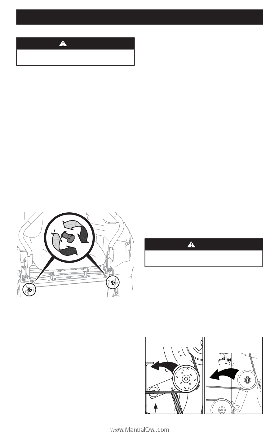
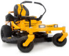
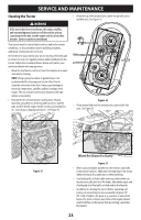
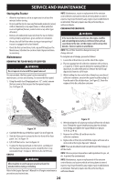
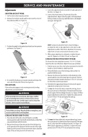
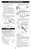
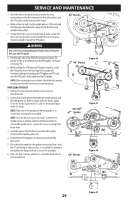
SERVICE AND MAINTENANCE ADJUSTING THE DECK WHEELS WARNING Keep hands and feet away from the discharge opening of the cutting deck. NOTE: The deck wheels are an anti-scalp feature of the deck and are not designed to support the weight of the cutting deck. The deck wheels should be approximately 1⁄4-1⁄2" (6.35-12.7 mm) above the ground when the deck is set in the desired height setting. To adjust the deck wheels, see the Assembly section for instructions. LAPBAR DRIVE CONTROL LEVER STOP ADJUSTMENT When the lapbar drive control levers are both fully extended forward to the full-speed position and the tractor drifts left or right, the lapbar drive control lever stop adjustment can be adjusted to sync the wheel speeds. To perform the adjustment, proceed as follows: 1. Identify the side that the tractor is drifting to and adjust the opposite lapbar drive control lever. If the tractor drifts right, adjust the left lapbar drive control lever down (decrease speed) and vice versa. 2. Locate the lapbar drive control lever stop adjustment bolts (a) on the front of the seat frame. See Figure 40. NOTE: The multi-tool (if equipped) can be used to make this adjustment. Service ELECTRICAL SYSTEM A fuse is installed to protect the tractor's electrical system from damage caused by excessive amperage. Always use the same capacity fuse for replacement. If the electrical system does not function, check for a blown fuse. If you have a recurring problem with blown fuses, have the tractor's electrical system checked by your authorized service dealer. RELAYS AND SWITCHES There are several safety switches in the electrical system. If a function of the safety interlock system described earlier is not functioning properly, have the electrical system checked by your authorized service dealer. PARKING BRAKE ADJUSTMENT If the tractor does not come to a complete stop when the control levers are moved fully outward engaging the parking brake or if the tractor's rear wheels can roll with the parking brake engaged (and the hydrostatic relief valve open), the brake is in need of adjustment. See your authorized service dealer to have the brake adjusted. DECK REMOVAL Remove the tractor deck from the tractor as follows: 1. Move the tractor to a level surface, disengage the PTO, stop the engine and place the RH and LH drive control levers fully outward into the park brake engaged position. 2. There are two methods for removing the belt, to remove the belt by releasing belt tension go on to Step 3, to remove the belt by rolling the belt off the PTO pulley skip ahead to Step 4. (a) Figure 40 3. To decrease the forward speed, turn the lapbar drive control lever stop adjustment bolts (a) clockwise. To increase the forward speed, turn the lapbar drive control lever stop adjustment bolts (a) counter-clockwise. Turn the lapbar drive control lever stop adjustment bolts (a) in the necessary direction 1⁄4-turn at a time. After turning the lapbar drive control lever stop adjustment bolts (a), check the adjustment by driving the tractor. See Figure 40. 4. Continue the adjustment until the wheel speeds are in sync and the tractor drives straight with the drive control levers fully extended forward in the full-speed position. NOTE: Make sure the bolts extend through the nuts on the frame to engage the locking feature. WARNING Use caution to avoid pinching your fingers when rolling the belt off the PTO pulley. 3. Releasing belt tension with the idler pulley: a. Using the deck lift handle or the deck lift pedal and knob, raise the deck to the position that provides the most horizontal run of the belt between the deck idler pulleys and the PTO pulley on the bottom of the engine. See Figure 41. b. Working from the middle of the tractor, pivot the idler bracket (a) and movable idler pulley (b) rearward just far enough to lift the belt up and over the spindle pulley. See Figure 41. 42" Decks 46/50/54/60" Decks (b) (b) (a) (a) 27 Figure 41
-
 1
1 -
2
-
3
-
4
-
5
-
6
-
7
-
8
-
9
-
10
-
11
-
12
-
13
-
14
-
15
-
16
-
17
-
18
-
19
-
20
-
21
-
 22
22 -
 23
23 -
 24
24 -
 25
25 -
 26
26 -
 27
27 -
 28
28 -
 29
29 -
 30
30 -
 31
31 -
 32
32 -
33
-
34
-
35
-
36
-
37
-
38
-
39
-
40
-
41
-
42
-
43
-
44
-
45
-
46
-
47
-
48
-
49
-
50
-
51
-
52
-
53
-
54
-
55
-
56
-
57
-
58
-
59
-
60
-
61
-
62
-
63
-
64
-
65
-
66
-
67
-
68
-
69
-
70
-
71
-
72
-
73
-
74
-
75
-
76
-
77
-
78
-
79
-
80
-
81
-
82
-
83
-
84
-
85
-
86
-
87
-
88
-
89
-
90
-
91
-
92
-
93
-
94
-
95
-
96
-
97
-
98
-
99
-
100
-
101
-
102
-
103
-
104
 |
 |