Cub Cadet ZT1 42 FAB Operation Manual - Page 26
Adjustments
 |
View all Cub Cadet ZT1 42 FAB manuals
Add to My Manuals
Save this manual to your list of manuals |
Page 26 highlights
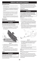
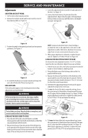
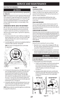
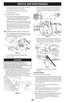
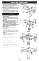
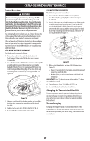
SERVICE AND MAINTENANCE Adjustments ADJUSTING DECK LIFT PEDAL 1. Set the deck to the transport position. 2. Remove the hex bolt, washer and hex nut near the center of the pedal assembly. See Figure 36. 3. Locate the adjustment bolts (a) on the left and right side of the deck. See Figure 38. 4. Loosen, but do not remove, the jam nuts (b) on the adjustment bolt. Adjust either the right or left adjustment bolt up or down as necessary until the side-to-side heights are equal. See Figure 38. (a) (b) Figure 36 3. Position the pedal to the optimal position based on operator preference. See Figure 37. Figure 37 4. Re-install the hardware previously removed and torque the nut to 28-35 ft-lbs (38-47 N-m). See Figure 36. DECK LEVELING If the cutting deck appears to be mowing unevenly, leveling adjustments can be performed. WARNING If the tractor has been recently run, the engine, muffler, and surrounding metal surfaces will be very hot and can cause burns to the skin. Let the engine cool for at least five minutes. Exercise caution to avoid burns. Figure 38 NOTE: Continue to check the front-to-back leveling as you make the side-to-side adjustment as the side-to-side adjustment can affect the front-to-back level. If necessary, adjust front-to-back as instructed in the next section. 5. When proper adjustment is achieved, re-tighten the jam nuts (b). Tighten to 57 ft-lbs (77 N-m). See Figure 38. LEVELING THE DECK (PITCH/FRONT-TO-REAR) The front of the deck should be between 1⁄16-1⁄4" (2-6 mm) lower than the rear of the deck. Adjust if necessary as follows: 1. Park the tractor on a firm, level surface and place the deck lift handle or deck lift knob in a middle position. 2. Rotate the blade nearest the discharge chute so that it is parallel with the tractor. 3. Measure the distance from the front of the blade tip to the ground and the rear of the blade tip to the ground. The first measurement taken should be between 1⁄16-1⁄4" (2-6 mm) less than the second measurement. 4. Determine the approximate distance necessary for proper adjustment and proceed, if necessary. 5. To raise the front of the deck, remove the end cap, loosen the outer jam nut (a) then tighten (thread inward) the inner nut (b) against the front hanger bracket. See Figure 39. When proper adjustment is achieved, re-tighten the outer jam nut (a) to 57 ft-lbs (77 N-m) and replace the end cap. (a) WARNING Tractor blades are sharp. Wrap the blade or wear gloves, and (b) use extra caution when servicing them. LEVELING THE DECK (SIDE-TO-SIDE) 1. Place the deck lift handle or deck lift knob in a middle mowing position and rotate both outside blades so that they are perpendicular with the tractor. 2. Measure the distance from the outside of the left blade tip to the ground and the distance from the outside of the right blade tip to the ground. Both measurements taken should be equal. If they are not, proceed to the next step. Figure 39 6. To lower the front of the deck, remove the end cap, loosen the outer jam nut (a) then loosen (thread outward) the inner nut (b), away from the front hanger bracket. See Figure 39. When proper adjustment is achieved, re-tighten the outer jam nut (a) to 57 ft-lbs (77 N-m) and replace the end cap. 26
-
 1
1 -
2
-
3
-
4
-
5
-
6
-
7
-
8
-
9
-
10
-
11
-
12
-
13
-
14
-
15
-
16
-
17
-
18
-
19
-
20
-
 21
21 -
 22
22 -
 23
23 -
 24
24 -
 25
25 -
 26
26 -
 27
27 -
 28
28 -
 29
29 -
 30
30 -
 31
31 -
32
-
33
-
34
-
35
-
36
-
37
-
38
-
39
-
40
-
41
-
42
-
43
-
44
-
45
-
46
-
47
-
48
-
49
-
50
-
51
-
52
-
53
-
54
-
55
-
56
-
57
-
58
-
59
-
60
-
61
-
62
-
63
-
64
-
65
-
66
-
67
-
68
-
69
-
70
-
71
-
72
-
73
-
74
-
75
-
76
-
77
-
78
-
79
-
80
-
81
-
82
-
83
-
84
-
85
-
86
-
87
-
88
-
89
-
90
-
91
-
92
-
93
-
94
-
95
-
96
-
97
-
98
-
99
-
100
-
101
-
102
-
103
-
104
 |
 |
