Cub Cadet ZT1 42 FAB Operation Manual - Page 9
Battery Information
 |
View all Cub Cadet ZT1 42 FAB manuals
Add to My Manuals
Save this manual to your list of manuals |
Page 9 highlights
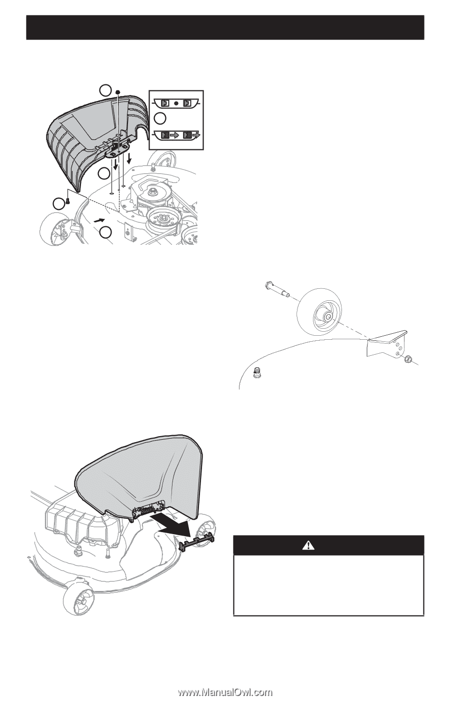
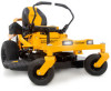
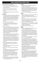
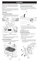
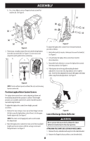
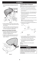
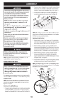
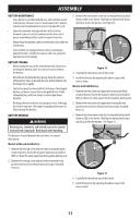
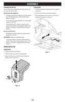
ASSEMBLY 3. Place the chute deflector on the deck, be sure to insert the tabs on the chute deflector into the holes on the deck. See Figure 9. 5 4 3 5 4 Figure 9 4. Slide the chute deflector toward the rear of the tractor until the bolt hole in the chute deflector aligns with the hole in the deck. See Figure 9. 5. Secure the chute deflector in place with the flange lock nut and hex screw removed in Step 2. Tighten to 102-124 in-lbs (11.5-14 N-m). Skip ahead to Setting Deck Wheels. REMOVING THE STOP BRACKET (IF NECESSARY) 1. If the chute is shipped attached and with a stop bracket holding the chute upright, the stop brackets must be removed prior to operating the tractor. 2. Holding the chute deflector fully upward, remove the stop bracket. Lower the chute deflector and discard the stop bracket. See Figure 10. Setting Deck Wheels (If Equipped) NOTE: The deck wheels are an anti-scalp feature of the deck and are not designed to support the weight of the cutting deck. 1. Move the tractor to a level surface, preferably pavement. 2. Check tire pressure, adjust if necessary. See tire side wall for proper tire pressure. 3. Make sure the deck is level side-to-side and properly pitched. See the Service and Maintenance section for deck leveling information and instructions. 4. Place deck lift lever or knob in the desired mowing height position and lower deck. 5. Check the wheels for contact or excessive clearance with the surface below. NOTE: The deck wheels should have between 1⁄4" (6.35 mm) and 1⁄2" (12.7 mm) clearance above the ground. 6. Remove the lock nut (a), gauge wheel (b) and shoulder screw (c) from the deck. See Figure 11. (c) (b) (a) Figure 11 7. Insert the shoulder screw into one of four index holes on the deck wheel bracket. Allow a 1⁄4-1⁄2" (6.35-12.7 mm) clearance between the ground and gauge wheel. 8. Note the index hole used on previously adjusted wheel. Repeat adjustment on opposite side to align both gauge wheels. NOTE: Refer to Adjustments section of this manual for more detail. Battery Information Figure 10 WARNING California PROPOSITION 65 WARNING: Battery posts, terminals, and related accessories contain lead and lead compounds, chemicals known to the State of California to cause cancer and reproductive harm. Wash hands after handling. 9
-
 1
1 -
2
-
3
-
 4
4 -
 5
5 -
 6
6 -
 7
7 -
 8
8 -
 9
9 -
 10
10 -
 11
11 -
 12
12 -
 13
13 -
 14
14 -
15
-
16
-
17
-
18
-
19
-
20
-
21
-
22
-
23
-
24
-
25
-
26
-
27
-
28
-
29
-
30
-
31
-
32
-
33
-
34
-
35
-
36
-
37
-
38
-
39
-
40
-
41
-
42
-
43
-
44
-
45
-
46
-
47
-
48
-
49
-
50
-
51
-
52
-
53
-
54
-
55
-
56
-
57
-
58
-
59
-
60
-
61
-
62
-
63
-
64
-
65
-
66
-
67
-
68
-
69
-
70
-
71
-
72
-
73
-
74
-
75
-
76
-
77
-
78
-
79
-
80
-
81
-
82
-
83
-
84
-
85
-
86
-
87
-
88
-
89
-
90
-
91
-
92
-
93
-
94
-
95
-
96
-
97
-
98
-
99
-
100
-
101
-
102
-
103
-
104
 |
 |