Dell Brocade 6520 Brocade 6520 Hardware Referencce Manual - Page 15
Brocade 6520 components, Port side of the Brocade 6520
 |
View all Dell Brocade 6520 manuals
Add to My Manuals
Save this manual to your list of manuals |
Page 15 highlights
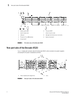
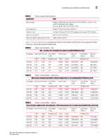
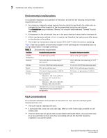
Port side of the Brocade 6520 1 • Local port latency minimized to 700 nanoseconds (ns) through the use of cut-through frame routing at 16 Gbps. • Switch latency of 2100 ns (L2 latency without forward error correction) Brocade 6520 components • A system motherboard that features a primary CPU running at 1.20 GHz, with integrated peripherals. • One 2 GB DDR2 running at 400 MHz. • Boot memory of 8 MB. • One 2 GB compact flash card. • Up to 96 16 Gbps Fibre Channel ports. • An RJ45 10/100/1000 BaseT Ethernet system management port (RJ45 connector), in conjunction with EZSwitchSetup, that supports switch IP address discovery and configuration, eliminating the need to attach a serial cable to configure the switch IP address. • One RS-232 console (serial) port with an RJ45 connector for initial switch setup (if not using EZSwitchSetup) and factory default restoration. • One USB 2.0 port that provides storage for firmware updates, output of the supportSave command, and storage for configuration uploads and downloads. • Two hot-swappable, 80+ Platinum certified, redundant power supplies. • Three hot-swappable fan FRUs. • One LED (green/amber) per FC port to indicate status. • One LED (green) for system power. • One LED (green/amber) for system status. • Two Ethernet LEDs (integrated with RJ45) for speed and activity status. • Two LEDs per power supply: one green for AC line in status and one green/amber for DC power out. • One LED (green/amber) per fan. • SEEPROM for switch identification. • Voltage monitoring. • Fan monitoring including flow direction. • Temperature monitoring. • Real-time clock (RTC) with battery. Port side of the Brocade 6520 The port side of the Brocade 6520 includes the system status LED, console port, Ethernet port and LEDs, USB port, and Fibre Channel ports and the corresponding port status LEDs. Figure 1 shows the port side of the Brocade 6520. Brocade 6520 Hardware Reference Manual 3 53-1002705-01
-
 1
1 -
2
-
3
-
4
-
5
-
6
-
7
-
8
-
9
-
 10
10 -
 11
11 -
 12
12 -
 13
13 -
 14
14 -
 15
15 -
 16
16 -
 17
17 -
 18
18 -
 19
19 -
 20
20 -
21
-
22
-
23
-
24
-
25
-
26
-
27
-
28
-
29
-
30
-
31
-
32
-
33
-
34
-
35
-
36
-
37
-
38
-
39
-
40
-
41
-
42
-
43
-
44
-
45
-
46
-
47
-
48
-
49
-
50
-
51
-
52
-
53
-
54
-
55
-
56
-
57
-
58
-
59
-
60
-
61
-
62
-
63
-
64
-
65
-
66
-
67
-
68
-
69
-
70
 |
 |