Dell Brocade 6520 Brocade 6520 Hardware Referencce Manual - Page 33
POST and boot-up specifications, POST, Boot-up
 |
View all Dell Brocade 6520 manuals
Add to My Manuals
Save this manual to your list of manuals |
Page 33 highlights
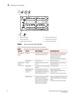
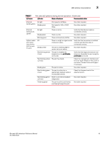
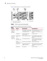
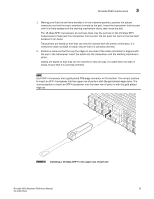
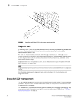
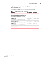
POST and boot-up specifications 3 TABLE 8 LED name Non-port side LED patterns during normal operation (Continued) LED color Status of hardware Recommended action Fan assembly status (one bi-color LED) No light Steady green Steady amber (for more than 5 seconds) Fan assembly is not receiving power. Verify that the fan FRU is seated correctly. Fan assembly is operating normally. No action required. Fan fault for one of the following reasons: • A fan assembly with mismatched airflow is present. • One or more of the fans in the fan assembly has failed. Try one of the following: • Replace the mismatched fan assembly with one that has the correct airflow direction. • Replace the faulty fan assembly. POST and boot-up specifications When the switch is turned on or rebooted, the switch performs power-on self-test (POST). Total boot-up time with POST can be several minutes. POST can be omitted after subsequent reboots by using the fastboot command or entering the diagDisablePost command to persistently disable POST. For more information about these commands, refer to the Fabric OS Command Reference. POST The success or failure results of the diagnostic tests that run during POST can be monitored through LED activity, the error log, or the command line interface. POST includes the following tasks: • Conducts preliminary POST diagnostics. • Initializes the operating system. • Initializes hardware. • Runs diagnostic tests on several functions, including circuitry, port functionality, memory, statistics counters, and serialization. Boot-up In addition to POST, boot includes the following tasks after POST is complete: • Performs universal port configuration. • Initializes links. • Analyzes fabric. If any ports are connected to other switches, the switch participates in a fabric configuration. • Obtains a domain ID and assigns port addresses. • Constructs unicast routing tables. • Enables normal port operation. Brocade 6520 Hardware Reference Manual 21 53-1002705-01
-
 1
1 -
2
-
3
-
4
-
5
-
6
-
7
-
8
-
9
-
10
-
11
-
12
-
13
-
14
-
15
-
16
-
17
-
18
-
19
-
20
-
21
-
22
-
23
-
24
-
25
-
26
-
27
-
 28
28 -
 29
29 -
 30
30 -
 31
31 -
 32
32 -
 33
33 -
 34
34 -
 35
35 -
 36
36 -
 37
37 -
 38
38 -
39
-
40
-
41
-
42
-
43
-
44
-
45
-
46
-
47
-
48
-
49
-
50
-
51
-
52
-
53
-
54
-
55
-
56
-
57
-
58
-
59
-
60
-
61
-
62
-
63
-
64
-
65
-
66
-
67
-
68
-
69
-
70
 |
 |
