Dell Brocade 6520 Brocade 6520 Hardware Referencce Manual - Page 30
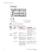
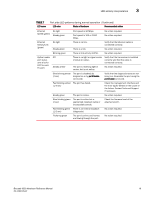
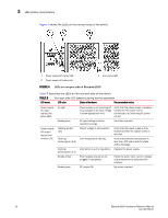
TABLE 7, LED activity interpretation, describes the port side LEDs and their behavior.
 |
View all Dell Brocade 6520 manuals
Add to My Manuals
Save this manual to your list of manuals |
Page 30 highlights
3 LED activity interpretation 1 System power LED 2 System status LED 3 FC port status LED (port 0) 4 FC port status LED (port 4) 5 Ethernet port activity LED 6 Ethernet port speed LED FIGURE 3 LEDs on port side of Brocade 6520 Table 7 describes the port side LEDs and their behavior. TABLE 7 Port side LED patterns during normal operation LED name LED color Status of hardware Recommended action Power Status No light (green) Steady green System Status (bicolor amber/green) No light Steady green Steady amber (for more than five seconds) The switch is off or there is an internal power supply failure. Verify that the system is powered on, the power cables are attached, and your power source is live. The unit may be faulty. Contact your switch service provider. The switch is on. No action required. The switch is off or there is no power. Verify that the system is on and has completed booting. The switch is on and functioning No action required. properly. A system fault has occurred. This LED displays steady amber during POST; this is normal and does not indicate a fault. Power cycle the switch. Check the failure indicated on the system console. Contact your switch service provider. Blinking amber Attention is required. A number of variables can cause this status including a single power supply failure, a fan failure, or one or more environmental ranges has been exceeded. Check the management interface and the error log for details on the cause of status. Contact your switch service provider. 18 Brocade 6520 Hardware Reference Manual 53-1002705-01
-
 1
1 -
2
-
3
-
4
-
5
-
6
-
7
-
8
-
9
-
10
-
11
-
12
-
13
-
14
-
15
-
16
-
17
-
18
-
19
-
20
-
21
-
22
-
23
-
24
-
 25
25 -
 26
26 -
 27
27 -
 28
28 -
 29
29 -
 30
30 -
 31
31 -
 32
32 -
 33
33 -
 34
34 -
 35
35 -
36
-
37
-
38
-
39
-
40
-
41
-
42
-
43
-
44
-
45
-
46
-
47
-
48
-
49
-
50
-
51
-
52
-
53
-
54
-
55
-
56
-
57
-
58
-
59
-
60
-
61
-
62
-
63
-
64
-
65
-
66
-
67
-
68
-
69
-
70
 |
 |
