Dell Brocade 6520 Brocade 6520 Hardware Referencce Manual - Page 23
Creating a serial connection, ATTENTION, TABLE 6
 |
View all Dell Brocade 6520 manuals
Add to My Manuals
Save this manual to your list of manuals |
Page 23 highlights
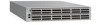
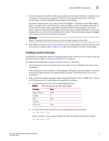
Brocade 6520 configuration 2 1. Connect the power cords first to both power supplies in the chassis and then to power sources on separate circuits to protect against AC failure. Ensure that the cords have a minimum service loop of 6 inches available and are routed to avoid stress. The power supplies power up as soon as they are plugged in. The power supply LEDs display green. The power LED on the front of the switch turn green as well. The system status LED on the front panel will be amber until POST completes and then it will turn green. If a second power supply is installed but NOT plugged into a power source, the AC status light on the power supply will be out and the DC status light will be amber. If the second power supply IS plugged into a power source, then both LEDs will be green. ATTENTION Power is supplied to the switch as soon as the first power supply is connected. 2. After POST is complete, verify that the switch power and status LEDs on the left of the port side of the switch are green. Refer to Figure 1 on page 4 for the specific location of these LEDs. Creating a serial connection You perform all configuration tasks in this guide using a serial connection. If you need to know the serial port pinouts, refer to "Serial port specifications" on page 41. Complete the following steps to create a serial connection to the switch. 1. Connect the serial cable to the serial port on the switch and to an RS-232 serial port on the workstation. If the serial port on the workstation is RJ45 instead of RS-232, remove the adapter on the end of the serial cable and insert the exposed RJ45 connector into the RJ45 serial port on the workstation. 2. Open a terminal emulator application (such as HyperTerminal on a PC, or TERM, TIP, or Kermit in a UNIX environment), and configure the application as follows: • In a Windows environment use the following parameters: TABLE 6 Windows terminal emulator parameters Parameter Bits per second Databits Parity Stop bits Flow control Value 9600 8 None 1 None • In a UNIX environment using TIP, enter the following string at the prompt: tip /dev/ttyb -9600 If ttyb is already in use, use ttya instead and enter the following string at the prompt: tip /dev/ttya -9600 Brocade 6520 Hardware Reference Manual 11 53-1002705-01
-
 1
1 -
2
-
3
-
4
-
5
-
6
-
7
-
8
-
9
-
10
-
11
-
12
-
13
-
14
-
15
-
16
-
17
-
 18
18 -
 19
19 -
 20
20 -
 21
21 -
 22
22 -
 23
23 -
 24
24 -
 25
25 -
 26
26 -
 27
27 -
 28
28 -
29
-
30
-
31
-
32
-
33
-
34
-
35
-
36
-
37
-
38
-
39
-
40
-
41
-
42
-
43
-
44
-
45
-
46
-
47
-
48
-
49
-
50
-
51
-
52
-
53
-
54
-
55
-
56
-
57
-
58
-
59
-
60
-
61
-
62
-
63
-
64
-
65
-
66
-
67
-
68
-
69
-
70
 |
 |